Deploy Drift Correction Feature in Solution (Automatic)
This section describes how to automatically deploy the drift correction feature in an ETH vision system. First, manually validate the central image-capturing point on the lowest layer of the workspace. Then generate the remaining image-capturing points and run the robot program to validate each point in sequence.
Deployment Process Overview
The automatic deployment process is shown below.

-
Learn about the deployment prerequisites: Learn about the prerequisites for deploying “Auto-correct accuracy drift in ETH vision system”.
-
Complete the preparations: Check the materials, mount the calibration sphere, warm up the camera, and check the robot workspace and motion paths.
-
Collect workstation data: Connect to the camera, select the project and parameter groups, and set the calibration sphere dimensions and deployment workflow.
-
Validate the reference image-capturing point: Move the robot to the central image-capturing point on the lowest layer of the workspace and validate the repeatability of the calibration sphere poses.
-
Generate image-capturing points and export program: Generate all image-capturing points based on the workstation data and reference point, check the planning results, and export the robot program.
-
Automatically validate image-capturing points: Configure and start the interface service, then run the robot program to validate the repeatability of the calibration sphere poses at each point in sequence.
-
Enable auto-correction: Enable auto-correction in the picking project, check and test the robot auto-correction program, and set the auto-correction interval in the program.
-
Check deployment result: Check the deployment result of “Auto-correct accuracy drift in ETH vision system”.
Deployment Prerequisites
The following prerequisites should be met before deployment:
-
A vision solution for picking has been deployed for the workstation.
-
The camera, robot, and extrinsic parameter accuracy checks have been completed, and the robot can pick target objects successfully. For instructions, refer to Error Analysis Tool.
-
Space has been reserved at the robot end for mounting the calibration sphere.
-
The Auto deployment method is available for the robot on the tool’s home page. If it is unavailable, use the manual deployment process.
Preparations
-
Check the materials and mount the calibration sphere.
Check that the ETH calibration sphere kit contains all required materials, and mount the calibration sphere as required.
-
Warm up the camera.
Use the Warm Up Tool to warm up the camera and prevent temperature increases during data acquisition from affecting intrinsic parameter accuracy.
-
Check the workspace and motion paths.
Check the robot workspace and motion paths, and remove any trays, bins, or other obstacles that may interfere with validation.
|
Automatically generated image-capturing points do not guarantee safe robot paths. Before running the robot program, check the reachability of each point and the motion paths. Run the robot at low speed to ensure that the robot, tool, and calibration sphere do not collide with surrounding objects. |
Start Deployment
-
Open the Auto-correct accuracy drift in ETH vision system tool.
On the menu bar, select to open the deployment tool.
-
Select automatic deployment.
In the Deployment wizard area on the tool’s home page, select the robot type and model. Select Auto under Deployment method and robot control mode, then click Start deployment to enter the automatic deployment process.
Collect Workstation Data
Connect to a Camera
-
Connect to the camera.
Click Connect to camera to select and connect to the camera used in the picking project.
-
Select the project and parameter groups.
Select the picking project that requires drift correction and the corresponding Calibration parameter group and Configuration parameter group to specify the project and camera configuration for this deployment.
Set Calibration Sphere Dimensions
-
Set the calibration sphere diameter.
Set Calibration sphere diameter according to the sphere in use. For a sphere with a diameter other than 60 mm, select Custom and enter the actual diameter.
Select Deployment Workflow
-
Select the workflow type.
Set Workflow type according to the on-site conditions to determine the number of image-capturing points to plan for each layer.
-
Simplified workflow: Plans 3 image-capturing points per layer. This workflow is suitable for a single target object located near the center of the camera’s field of view. If the distance from the calibration sphere at its lowest limit position to the lowest-layer target object exceeds 200 mm, select Standard workflow.
-
Standard workflow: Plans 9 image-capturing points per layer. This workflow is suitable for multiple target objects, objects distributed across the camera’s field of view, or objects away from the center of the field of view.
-
After completing the settings, click Next to validate the reference image-capturing point.
Validate the Reference Image-Capturing Point
The reference image-capturing point is the central point on the lowest layer of the workspace and is used to generate subsequent image-capturing points.
-
Move the robot to the reference image-capturing point.
Manually move the robot at low speed to the central image-capturing point on the lowest layer of the workspace. Ensure that the camera can capture the entire calibration sphere.
-
Check the robot joint angles.
In the Joint angles area, check the current joint angle of each robot axis. To make changes, click the edit icon and enter the actual values. Ensure that the selected robot model and joint angles match the on-site robot.
-
Set the calibration sphere ROI.
Click Set ROI and outline the calibration sphere. Ensure that the ROI fully encloses the sphere, leaving a margin equal to the sphere’s diameter on all sides.
-
Validate the reference image-capturing point.
Click Capture image to validate to validate the repeatability of the calibration sphere poses at this point and confirm that the reference point can be used to plan subsequent points.
If the calibration sphere is not detected, check that the entire sphere is within the camera’s field of view and the ROI. Adjust the ROI as needed and validate again.
-
Proceed to image-capturing point generation.
After the reference image-capturing point passes validation, click Next to generate image-capturing points and export the program.
Generate Image-Capturing Points and Export Program
Select Scenario
-
Set the target object layout.
Under Scene, select Random stacked or Multilayer arrangement according to the on-site conditions. If you select Multilayer arrangement, also set the number of layers.
-
Set the distance from the calibration sphere at its lowest limit position to the lowest-layer target object.
When Random stacked is selected, set Distance from lowest sphere to lowest object. This is the distance between the calibration sphere center and the lowest-layer target object when the robot moves the sphere to its achievable lowest position, as shown below.
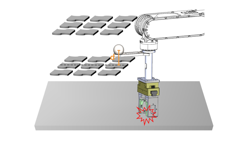
-
Set the target point cloud space dimensions.
Set the length, width, and height of Space dimensions of target point cloud according to the extent of the target point cloud actually used for localization.
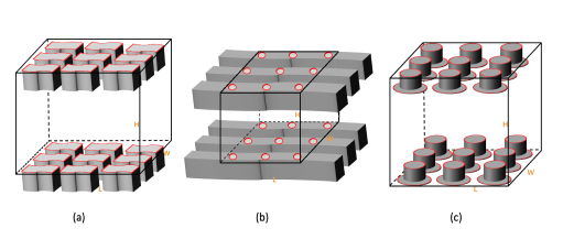
(a) If matching uses the point cloud of the object’s upper surface, the target point cloud height is the distance from the upper surface of the highest-layer object to the upper surface of the lowest-layer object.
(b) If matching uses a local point cloud of the object’s upper surface, the target point cloud height is the distance from the upper surface of the highest-layer object to the upper surface of the lowest-layer object.
(c) If matching uses point clouds of multiple object surfaces at different heights, the target point cloud height is the distance from the upper surface of the highest-layer object to the lower surface of the lowest-layer object.
-
For a single layer of objects, if matching uses the point cloud of the object’s upper surface, the target point cloud height is 0.
-
If partitions exist between object layers, the target point cloud height should include the partition heights.
-
-
Set the rotation angle around the Z-axis and generate image-capturing points.
Set Rotation angle around Z-axis according to the on-site requirements, then click Generate image-capturing points. The tool generates all points based on the scene settings and reference image-capturing point.
Rotation angle around Z-axis is the angle by which the workspace reference frame rotates around the Z-axis relative to the robot reference frame after the robot reference frame is translated to the workspace origin.
Check Planning Results
-
Check the image-capturing point planning parameters.
On the image-capturing point planning results tab, check the distance from the lowest sphere to the lowest object, the distance between two layers, the same-layer lengthwise spacing between spheres, the same-layer widthwise spacing between spheres, and the total number of layers.
-
Check the spatial distribution of image-capturing points.
Switch to the Scene visualization results tab and check that the point distribution matches the actual workstation. If scene parameters need adjustment, modify them and regenerate the image-capturing points before exporting the program.
Export and Load the Robot Program
-
Export the robot program.
In the Generate robot program area, click Export to obtain the robot program for moving to the planned image-capturing points.
-
Check and adjust the robot program.
Check the robot IP address, robot reference frame, tool, Home position, image-capturing points, and communication parameters in the exported program. Adjust them as needed to match the actual workstation.
-
Load the robot program.
Load the adjusted program to the robot. For FANUC robots, compile the program into a TP file first as required by the robot.
For instructions, refer to “Standard Interface Communication Configuration” for the corresponding robot brand in Standard Interface Communication.
-
Proceed to automatic validation.
After loading the program, click Next to configure the interface service and automatically validate the image-capturing points.
|
After loading the program, check each motion path before running the robot at low speed. If image-capturing points are regenerated or adjusted, update the corresponding points in the robot program. Do not use an outdated program to validate new points. |
Automatically Validate Image-Capturing Points
Start Interface Service
-
Set the interface communication parameters.
In the Start interface service area, select the communication method that matches the robot program and set the host IP address and port number. Ensure that the robot and IPC can communicate over the network and that the program’s communication settings match these settings.
-
Check the robot-side configuration instructions as needed.
For robot-side configuration instructions, click the Robot Communication Configuration Guide link in the interface and follow the corresponding instructions.
-
Start the interface service and establish a connection.
Click Start interface service and run the loaded program on the robot. Confirm that the connection is established before validation.
Capture Image to Validate
-
Run the program and validate the current image-capturing point.
Run the robot program at low speed. The robot moves to an image-capturing point according to the program and pauses upon arrival to validate the repeatability of the calibration sphere poses.
-
Check the validation result for the current point.
On the Validation results tab, check the status of the current point. After validation, click View in the corresponding row to check the result.
-
Continue running the program to validate the remaining points.
After the current point is validated, resume the program on the robot teach pendant. The robot moves to the next point. Check each path and complete validation until all points pass.
-
Proceed to auto-correction configuration.
After all image-capturing points pass validation, click Next to configure auto-correction for production.
|
If a point is unreachable or presents a collision risk, stop the robot first. Then manually move it to a nearby safe, reachable point where the calibration sphere is visible. Update the corresponding point in the robot program, return to that point, and validate again. Do not continue running the program until the risk has been eliminated. |
If validation fails, click View to check the result. Ensure that the entire sphere can be imaged and is within the ROI, resolve the issue, and validate again. You can switch to the Scene visualization results tab to view the spatial distribution of image-capturing points.
Enable Auto-Correction
After validating the image-capturing points, enable auto-correction in the picking project. Check, adjust, and test the robot auto-correction program so that it can periodically correct accuracy drift during production.
Enable Auto-Correction in Picking Project
Select Auto-Correct Accuracy Drift in Vision System in the Output or Path Planning Step of the picking project to enable auto-correction.
Adjust Robot Program
Check and adjust the robot auto-correction program as needed. Ensure that the communication parameters, project numbers, recipe numbers, reference frame, tool, Home position, and image-capturing points match the on-site conditions. If points were adjusted during automatic validation, update the robot program used for production accordingly.
For the program workflow, FANUC example program, and key statement descriptions, refer to Adjust Robot Program in the manual deployment process.
Load Robot Program
If the previously loaded program has been modified, reload the updated program to the robot after completing program adjustments and checking the points, then perform a test run. For FANUC robots, compile the program into a TP file first. If the program has not been modified, it does not need to be loaded again.
|
For instructions on loading the auto-correction program, refer to “Standard Interface Communication Configuration” for the corresponding robot brand in Standard Interface Communication. |
Test Robot Program
Confirm that the updated auto-correction program has been loaded to the robot. Then test it at low speed, checking each motion path to ensure that the robot does not collide with target objects or surrounding equipment. The robot moves to the corresponding image-capturing points, triggers the drift correction projects to capture images and collect calibration sphere poses, and corrects drift based on the generated drift correction data.
|
For instructions on selecting and testing the auto-correction program, refer to “Standard Interface Communication Configuration” for the corresponding robot brand in Standard Interface Communication. |
After the robot auto-correction program runs, correction records are generated and can be viewed on the Data Monitoring Dashboard.
Test Pick
Run the robot picking program and check the picking results. If the robot can pick target objects accurately, the deployment is successful.
After the test pick, configure the drift alert threshold on the Data Monitoring Dashboard to ensure stable long-term production.
Determine Auto-Correction Interval
Set the auto-correction interval in the robot program according to the on-site conditions to collect calibration sphere poses periodically and correct accuracy drift.
The deployment of “Auto-correct accuracy drift in ETH vision system” is now complete. Click Finish to return to the tool’s home page.
|
The Drift_Collection_ETH and Drift_Calculation projects generated by the tool collect calibration sphere poses and generate drift correction data, respectively. Do not modify their contents, names, or project numbers. Do not modify the name or configuration of the automatically generated calibration sphere point cloud model. |
After deployment, it is recommended to export the current camera configuration parameter group to a local backup for subsequent quick camera replacement.
Check Deployment Result
-
Check the camera deployment information.
After deployment, click Check deployment at the bottom of the tool’s home page and select the camera to view the corresponding image-capturing point and recipe information.
-
Export the robot program again as needed.
If the previously exported auto-correction program is lost or needs to be exported again, select the corresponding brand from the robot brand drop-down list and click Export.