Automatic Calibration in the Eye-in-Hand Setup (Six-Axis Robot)
This how-to guide introduces how to complete the automatic hand-eye calibration for six-axis robots and 2D cameras in the eye-in-hand (EIH) setup.
Introduction to the Overall Process
The following figure shows the overall process of the automatic calibration for a six-axis robot in the eye-in-hand (EIH) setup.

-
Preparation before Calibration: Complete the required preparations before the calibration.
-
Configuration before Calibration: Complete the pre-calibration configuration, such as selecting the robot model and the camera setup.
-
Perform Calibration: Start the calibration and obtain the calibration result after completing a series of operation steps. In this step, you need to perform operations on the robot side to establish the communication between the vision system and the robot.
-
Validate Calibration Results: Validate the obtained calibration result to check whether the result meets the requirements.
-
Apply Calibration Result: You use the new calibration parameter group in the vision project.
The following sections describe the above process in detail.
Preparation before Calibration
Before hand-eye calibration, you need to finish the following preparations:
Complete the Camera Installation
Please refer to Camera Installation to complete the camera installation.
You need to use Mech-Vision & Mech-Viz during hand-eye calibration. Please ensure that they have been installed and are running the latest versions.
Complete the Robot Communication Configuration
If the robot uses the Standard Interface to communicate with the Vision System, please set up the Standard Interface communication with the robot. According to the robot brand used in your project, you can complete the Standard Interface communication configuration by referring to the “Set up Standard Interface Communication” guide for the corresponding robot brand in xref:2.2.1@robot-integration:standard-interface-robot:standard-interface-use-flow.adoc[Standard Interface Communication.
If the robot uses the Master-Control to communicate with the Vision System, please set up the Master-Control communication with the robot. According to the robot brand used in your project, you can complete the Master-Control communication configuration by referring to the “Set up Master-Control Communication” guide for the corresponding robot brand in vxref:2.2.1@robot-integration:full-control:full-control-use-flow.adoc[Master-Control Communication.
Prepare the Materials Required for Calibration
The automatic calibration in the ETH setup needs to use the calibration board or marker.
-
If a calibration board is used, please prepare according to the following requirements:
-
Ensure that the circles of the calibration board are clearly visible and without obvious scratches, and the board does not suffer from deformations.
-
In the ETH setup, mount the robot-specific bracket for calibration board onto the robot flange, and then mount the calibration board onto the bracket. Ensure that the calibration board is securely mounted, located at the center of the camera’s field of view, and as parallel as possible to the plane where the camera is located, i.e., as perpendicular as possible to the Z-axis of the camera reference frame.
-
You can refer to Calibration Board Selection to choose the appropriate calibration board model to improve calibration accuracy and stability.
-
If an undetachable gripper is connected to the robot flange, you can attach the calibration board directly to the gripper.
-
-
-
If a calibration board is not convenient to use on-site (due to space constraints or mounting difficulties), a marker can be used instead. Please prepare according to the following requirements:
-
The marker should have clearly visible feature points, and the feature points should be distributed as evenly as possible.
-
Check Calibration Board Image Quality
| The image quality of the calibration board will affect the accuracy of the hand-eye calibration results. Therefore, you need to check the image quality of the calibration board. The calibration process involves checking the image quality of the calibration board. You can also check the image quality of the calibration board in advance, thus saving time during the calibration process. |
-
Place the calibration board horizontally at the center of the working plane within the camera’s field of view.
-
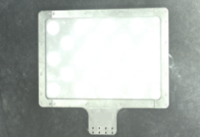
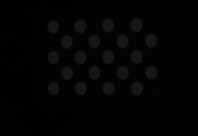
Connect to the camera and adjust camera parameters in the 2D Camera Management tool to ensure that the overall brightness of the calibration board in the 2D image is not too dark, too bright, or has uneven brightness, and each calibration circle is clearly visible.
If the on-site ambient light is complex, it is recommended to use shading or supplemental light to reduce the impact of ambient light on 2D images.
Normal Overexposed Underexposed 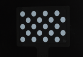
Complete Pre-calibration Checks
Please refer toPre-calibration Checks and complete the following checks:
-
Confirm that the robot base is mounted securely.
-
Confirm that the camera mounting frame and camera are mounted securely.
-
Confirm that the absolute accuracy of the robot meets the requirements for use.
-
Verify robot model parameters.
-
Confirm that the camera is undistorted or has undergone distortion calibration.
-
Confirm that the camera is warmed up.
Configuration before Calibration
-
Open Mech-Vision, and select in the menu bar. The Configuration before Calibration window will be prompted.
-
After confirming that pre-calibration checks are completed, click I’ve finished all checks, and then click Next.
-
In the Select how to calibrate window, select the New calibration radio button, and then click the Next button.
-
In the Select calibration task window, select Hand-eye calibration for listed robot from the drop-down list box, click the Select robot model button to select the robot model used by the project, and then click the Next button.
-
In the Select camera setup window, select the Eye in hand radio button, and then click the Next button.
-
In the Calibration method and robot control window, select Automatic and Standard Interface, and then click the Calibrate button. The Calibration (Eye in Hand) window will be prompted.
If the Master-Control is used to communicate with the robot, then select Automatic and Master-control.
At this point, the pre-calibration configuration is complete, and you will proceed to the calibration process.
Perform Calibration
Connect to Camera
-
Connect the camera.
In the Connect to camera step, select a connected camera from the drop-down list.
If there is no available camera in the list, you can click the 2D Camera Management button, complete the camera connection in the 2D Camera Management tool, and then return here to select the corresponding camera.
-
Confirm that the camera can capture images normally.
After the camera is connected, you can click the Capture live or capture once button to view the captured images in the right Image viewer panel.
When capturing images, ensure that the overall brightness of the captured calibration board is not too dark, too bright, or uneven, and that each calibration circle is clearly visible. If the image quality does not meet the requirements, you can adjust Exposure Time and Gain to improve the image quality.
-
Load the distortion calibration result.
To correct the distortion in the image and ensure that the subsequent hand-eye calibration is based on more accurate image coordinates, the distortion calibration result of the corresponding camera should be loaded, and the tool will correct the acquired image based on this result before performing the subsequent calibration.
If the camera is undistorted, you can omit this operation.
After the camera is connected and the image quality is confirmed, click the Next button on the bottom bar.
Select Calibration Method
The tool provides two calibration methods: Calibrate using calibration board and Calibrate using feature points. The details are as follows.
Use the Calibration Board
This method is suitable for scenarios that require high calibration accuracy or where no suitable marker is available.
-
In the drop-down menu of Calibration mode, select Calibrate using calibration board.
-
Based on the mark on the calibration board, select the model of the calibration board in use in the drop-down menu of “Standard Calibration Board Model”.
Use Feature Points for Calibration
This method is suitable for scenarios where a calibration board is inconvenient to use on-site (due to space constraints or mounting difficulties) and where there are already usable feature points on the marker.
|
If the target object has clear edges and is not completely symmetrical, it can be used as a marker. |
The tool provides two feature point calibration methods: 2D matching and Obtain from project. The details are as follows.
| Feature Point Recognition Method | Description | Operation |
|---|---|---|
2D matching |
Recognize feature points in an image through model matching.
|
Typical scenarios
|
Obtain from project |
This method obtains feature points through the processing flow in an existing vision project.
|
|
Connect the Robot
If the Standard Interface communication is used during calibration, please refer to Connect the Robot (Standard Interface).
If the Master-Control communication is used during calibration, please refer to Connect the Robot (Master-Control).
Connect the Robot (Standard Interface)
-
(Optional) In the Connect the robot step, click the Start interface service button. The button will turn intoWaiting for the robot to connect.... If the Standard Interface Communication option on the toolbar was previously enabled, this step is not necessary.
-
On the robot teach pendant, perform several operations: Select the automatic calibration program, teach the start point and run the program. After the program is started, the log message “Entering the calibration process, please start the calibration in Mech-Vision” will be printed in the Console log panel.
According to the robot brand used in your project, you can complete the operations on the robot side by referring to the “Automatic Calibration” guide for the corresponding robot brand in Standard Interface Communication.
Connect the Robot (Master-Control)
-
On the robot teach pendant, select and run the Master-Control program.
According to the robot brand used in your project, you can complete the operations on the robot side by referring to the “Set up Master-Control Communication” guide for the corresponding robot brand in Master-Control Communication.
-
In the Connect the robot step, set the Robot IP address parameter.
-
Click the Connect the robot button in the Connect the robot area. The button will turn into Waiting for the robot to connect...
-
Wait until the “Disconnect robot” status message is displayed in the Connect the robot area, and then click the Next button.
Set Motion Path
During calibration, the robot needs to move sequentially so that the camera and the calibration board form different positions and angles, thereby collecting sufficient spatial feature information. The entire motion path usually includes two types of motion:
Translational motion: The robot tool moves horizontally to a set of evenly distributed calibration points, from calibration point 1 to calibration point N.
Rotational motion (optional): After the translational motion is completed, the robot rotates several times around the Z-axis at the center of the motion path (for example, in a 3×3 path, where calibration point 5 is the center of the motion path) to supplement the orientation information.
Detailed operational instructions are as follows:
-
Set Translational Motion Parameters
-
Number of Translations: The number of translations determines the number and distribution range of sampling points during calibration. 3×3 suitable for scenarios requiring general accuracy and requiring rapid calibration; 5×5 provides higher spatial coverage and calibration accuracy, suitable for applications with large field of view or high accuracy.
-
Interval: The translation distance between two calibration points. The smaller the interval, the denser the calibration points, and the higher the calibration accuracy, but it takes longer. When the number of translations is "3×3", it is recommended to set the "Translation interval" to 1/4 to 1/8 of the Y field of view; when the number is "5×5", it is recommended to set it to 1/8 to 1/12 of the Y field of view.
-
-
Set Rotational Motion Parameters (Optional)
If the robot tool needs to rotate when picking the target object, it is recommended to perform rotational calibration.
-
Number of rotations: The number of rotations, usually at least 3.
-
Rotation angle: The angle change of each rotation relative to the previous one. Appropriate rotation angles can improve the accuracy of extrinsic parameter calculation.
-
After the adjustment, in the right Scene viewer panel, make sure that the waypoints are at proper positions and that the robot will not collide with surrounding objects when moving, and then click the Generate path based on parameters button.
After setting the motion path, click Next on the bottom bar.
Obtain Feature Points and Poses
| Before this step, please make sure that the current robot pose matches the real pose on the robot teach pendant. |
-
In the Obtain feature points and poses step, click the Start calibration button.
-
Read the safety window carefully and click the OK button.
-
Wait until the robot finishes moving along the preset path and the camera finishes acquiring images on all waypoints. A pop-up window will display the progress of moving to the calibration point.
Please stay away from the robot working area to keep safe. -
When the pop-up window says “All calibration points have been reached successfully, and the calibration is completed.”, click the Ok button.
-
Confirm that the collected calibration data meets the data requirements, and then click the Next button on the bottom bar.
If the requirements are not met, please manually move the robot (through the teach pendant or Mech-Viz), enable the Add more images manually option in the 3 Auxiliary tool, and click the Add images and record flange poses button to add the calibration board image and enter the robot flange pose.
Calculate Extrinsic Parameters
-
In the Calculate extrinsic parameters step, click the Calculate extrinsic parameters button in the Calculate extrinsic parameters and check results area.
-
In the prompted Calibration success dialog box, click OK to view the calibration result in the Messages panel below.
-
On the bottom bar of the Calculate extrinsic parameters step, click the Save button. A message saying “Calibration file saved successfully” will pop up in the message box, and the calibration result will be automatically saved to the “calibration” folder of the solution.
Apply Calibration Result
After validating the extrinsic parameters, you can apply the calibration result.
Select the 2D Smart Camera Step, enable the Enable calibration function in the Step Parameters panel, and then select the saved calibration result from the drop-down menu to apply the calibration result for subsequent visual processing and picking.
The calibration process is now complete.