Hand-Eye Calibration Principles
Hand-eye calibration is a commonly used method in robotic and vision systems, aimed at determining the transformation relationship between the camera reference frame and the robot end reference frame (typically the tool reference frame). By performing hand-eye calibration, the space in the vision system can be aligned with that of the robotic system, enabling tasks such as vision-guided operations and precise localization.
This section describes the relationships between various poses or points during hand-eye calibration.
|
Different forms of symbols are used to represent points and poses. The uppercase letter T denotes poses. For example, robotTflange represents the pose of the robot flange relative to the robot base. The lowercase letter p denotes points. For example, robotpboard-robot indicates the relationship of a reference point on the calibration board relative to the robot base. |
Hand-Eye Calibration in the ETH Setup (Multiple Random Calibration Board Poses)
When selecting the multiple random calibration board poses method for hand-eye calibration in ETH scenarios, the relationships among the poses of the camera, robot base, robot flange, and calibration board are illustrated as a closed loop in the following diagram.
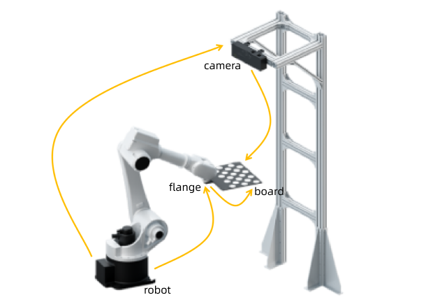
To better understand the relationships between poses expressed in the form of equations, you can refer to the table below to learn the representation methods for each relative pose.
| Pose | Relationship | Note |
|---|---|---|
robotTflange |
Pose of the robot flange relative to the robot base |
Available from the robot side |
cameraTboard |
Pose of the calibration board relative to the camera |
Can be obtained by capturing an image with the camera and calculating |
flangeTboard |
Pose of the calibration board relative to the robot flange |
Constant in the extrinsic parameter calibration, used for establishing the equations |
robotTcamera |
Pose of the camera relative to the robot base (extrinsic parameter) |
The result of the extrinsic parameter calibration, to be calculated |
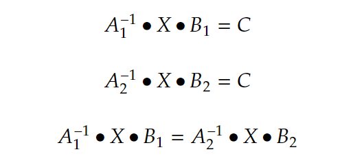
Based on the above diagram and the pose relationships mentioned, the following equations can be derived.
Hand-Eye Calibration in the EIH Setup (Multiple Random Calibration Board Poses)
When selecting the multiple random calibration board poses method for hand-eye calibration in EIH scenarios, the relationships among the poses of the camera, robot base, robot flange, and calibration board are illustrated as a closed loop in the following diagram.
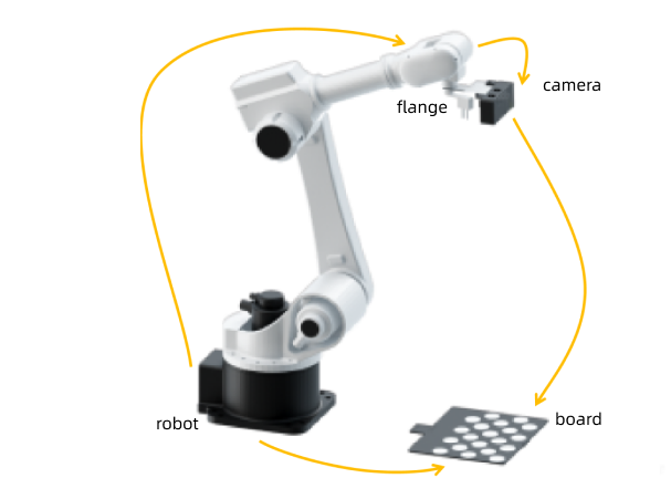
To better understand the relationships between poses expressed in the form of equations, you can refer to the table below to learn the representation methods for each relative pose.
| Pose | Relationship | Note |
|---|---|---|
robotTflange |
Pose of the robot flange relative to the robot base |
Available from the robot side |
cameraTboard |
Pose of the calibration board relative to the camera |
Can be obtained by capturing an image with the camera and calculating |
robotTboard |
Pose of the calibration board to the robot base |
Constant in the extrinsic parameter calibration, used for establishing the equations |
flangeTcamera |
Pose of the camera relative to the robot flange (extrinsic parameter) |
The result of the extrinsic parameter calibration, to be calculated |
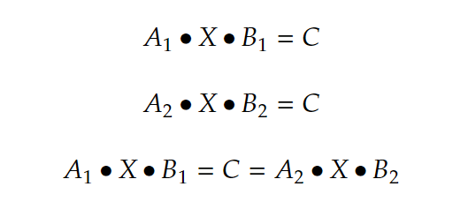
Based on the above diagram and the pose relationships mentioned, the following equations can be derived.
Hand-Eye Calibration in the ETH Setup (TCP Touch)
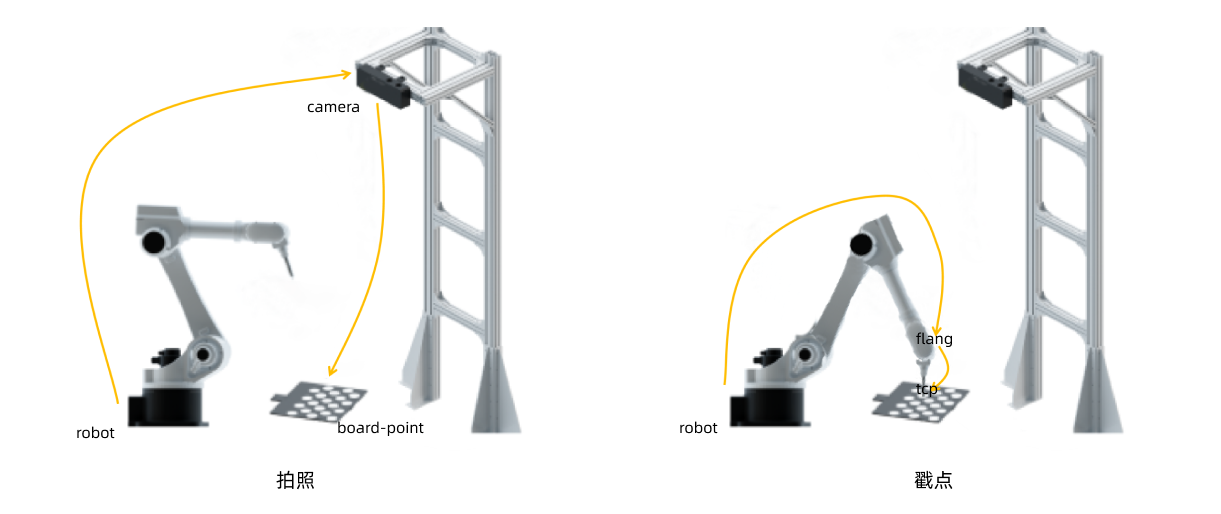
When selecting the TCP touch method for hand-eye calibration in ETH scenarios, the relative relationships among the poses/points during image capturing and TCP touch are illustrated as a closed loop in the following diagram.
To better understand the relationships between poses expressed in the form of equations, you can refer to the table below to learn the representation methods for each relative pose/point.
| Image capturing/TCP touch | Pose/point | Relationship | Note |
|---|---|---|---|
Image capturing |
camerapboard-point |
The reference point on the calibration board captured by the camera, reflecting the relationship between the reference point and the camera |
Can be obtained by capturing an image with the camera and calculating |
robotTcamera |
Pose of the camera relative to the robot base (extrinsic parameter) |
The result of the extrinsic parameter calibration, to be calculated |
|
TCP touch |
robotTflange |
Pose of the robot flange relative to the robot base during TCP touch |
Available from the robot side |
flangeptcp |
Robot TCP, which indicates the relationship between the tool end and the flange end. |
Constant in the extrinsic parameter calibration, used for establishing the equations |
|
robotptcp |
Robot TCP, which reflects the relationship between the TCP and the robot base during TCP touch. |
Can be calculated based on flangeptcp and robotTflange |
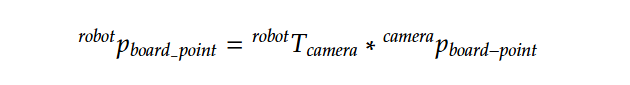
Based on the diagram and the relationships mentioned above, equations for both image capturing and TCP touch can be derived separately.
During image capturing, the relationship between the reference point on the calibration board and the robot base can be calculated using the known relationships described above.
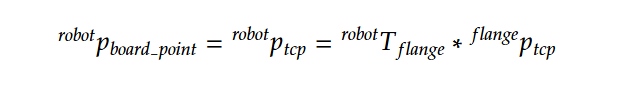
During TCP touch, the relationship between the reference point on the calibration board and the robot base can also be calculated using the known relationships described above.
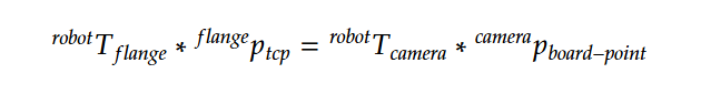
From these two equations, the following equation can be established.
Hand-Eye Calibration in the EIH Setup (TCP Touch)
When selecting the TCP touch method for hand-eye calibration in EIH scenarios, the relative relationships among the poses/points during image capturing and TCP touch are illustrated as a closed loop in the following diagram.
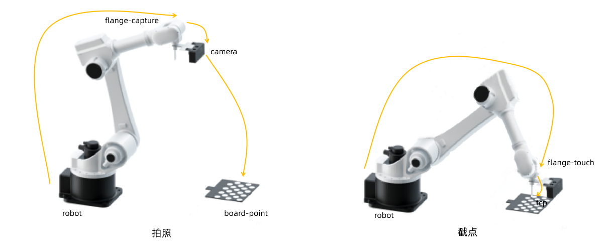
To better understand the relationships between poses expressed in the form of equations, you can refer to the table below to learn the representation methods for each relative pose/point.
| Image capturing/TCP touch | Pose | Relationship | Note |
|---|---|---|---|
Image capturing |
robotTflange-capture |
Pose of the robot flange relative to the robot base during image capturing |
Available from the robot side |
flange-captureTcamera |
Pose of the camera relative to the robot flange (extrinsic parameter) |
The result of the extrinsic parameter calibration, to be calculated |
|
camerapboard-point |
The reference point on the calibration board captured by the camera, reflecting the relationship between the reference point and the camera |
Can be obtained by capturing an image with the camera and calculating |
|
TCP touch |
robotTflange-touch |
Pose of the robot flange relative to the robot base during TCP touch |
Available from the robot side |
flange-touchptcp |
Robot TCP, which indicates the relationship between the tool end and the flange end. |
Constant in the extrinsic parameter calibration, used for establishing the equations |
|
robotptcp |
Robot TCP, which reflects the relationship between the TCP and the robot base during TCP touch. |
Can be calculated based on robotTflange-touch and flangeptcp |
Based on the diagram and the relationships mentioned above, equations for both image capturing and TCP touch can be derived separately.
During image capturing, the relationship between the reference point on the calibration board and the robot base can be calculated using the relationships described above.

During TCP touch, the relationship between the reference point on the calibration board and the robot base can also be calculated using the known relationships described above.
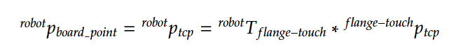
From these two equations, the following equation can be established.
