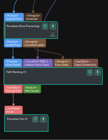
Path Planning
Function
This Step uses the input vision points to plan the robot path and outputs the successfully planned robot path.
|
The Path Planning Step feature is Mech-Viz-related and requires Mech-Viz installation and software licensing to use the Step. |
|
Usage Scenario
This Step is usually used in projects where the Standard Interface or Adapter is used for communication, and only the robot motion path near the vision point needs to be planned. After you build a scene and input the vision points, this Step will output a collision-free robot motion path after point cloud collision detection and path planning.
The common predecessors and successor of this Step are as follows:
-
Predecessors: Steps related to pose adjustment and pose processing.
-
Steps to follow: Output Step (with the "Output Type" parameter set to "Robot path for picking").
Input and Output
Input
| Input port | Data type | Description |
|---|---|---|
Pick Points |
Pose[] |
List of pick points of the target objects. |
Pick Point Info |
JsonValue |
Pick point related information, including target object names, pick point names, and pick point labels. |
Collision Point Cloud |
PointCloud[] |
Point cloud input to this port will be used for collision detection with the tool. (Point cloud collision detection should be enabled in the Path Planning Tool.) |
Pick Point Labels |
String[] |
Labels for pick points set in the target object editor, typically used for Standard Interface communication with the host computer. |
Target Object Dimensions |
Size3D[] |
The dimensions of the target object. |
Pick Point Offset |
Pose[] |
The offset of the pick point on the target object relative to the object center point. |
Scene Object Names |
String[] |
List of scene object names. The dimensions and poses of objects in this list will be updated. |
Scene Object Dimensions |
Size3D[] |
List of scene object dimensions. Scene object dimensions will be updated in list order. |
Scene Object Poses |
Pose[] |
List of scene object poses. Scene object poses will be updated in list order. |
Parameter Description
Path Planning Settings
| Parameter | Description |
|---|---|
Workflow Configuration |
Description: Open the path planning tool and select the configured workflow in the drop-down list. |
Update Scene Object |
Description: When this option is enabled, the Scene Object Names, Scene Object Dimensions, and Scene Object Poses input ports will be added for updating the poses and dimensions of scene objects such as the bin.
|
Usage Scenario
| Parameter | Description |
|---|---|
Select Scenario |
Description: Select the usage scenario of the current solution. Value list: 3D model matching (Machine Tending/Positioning/Assembly), Depalletizing and others Instruction:
Default value: 3D model matching (Machine Tending/Positioning/Assembly) |
Method to Convert Data |
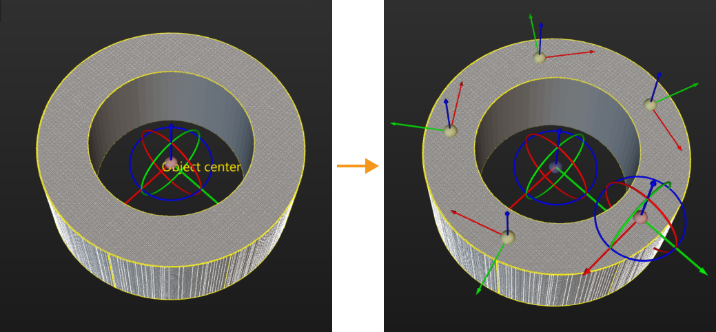
Description: By selecting the result conversion method, this Step converts the recognition result to the data type needed for picking. Value list: Generate picking strategy based on object center point, Generate picking strategy based on pick points
Default value: Generate picking strategy based on object center point |
Target Object without Point Cloud Model |
Description: Select a target object that does not require a point cloud model, and this Step can output pick point information for the target object. Please set this parameter when the usage scenario is “Depalletizing and Others”. |
Collision Detection Settings
| Parameter | Description |
|---|---|
Point Cloud in Camera Frame |
Description: Please select this parameter when the point cloud is in the camera reference frame. Once this option is selected, the point cloud will be converted to the robot reference frame and sent to the path planning tool. If this option is not selected, the point cloud will be sent to the path planning tool directly.
|
Remove Point Cloud of Irregular Shape |
Description: Once this option is enabled, any point cloud overlapping with the collision model of the target object with a non-standard 3D shape will be removed by Mech-Vision to prevent interference in collision detection. Please set this parameter when the usage scenario is “Matching (Machine Tending/Positioning/Assembly).”
|
Search Radius of Target Object Point Cloud |
Description: Take any point in the point cloud of the target object as the center, and the point cloud within the search radius will be removed. Please set this parameter when Remove Point Cloud of Irregular Shape is selected.
|
Other Ports
| Parameter | Description |
|---|---|
Pick Point Labels |
Description: When selected, a "Pick Point Labels" input port is added.
|
Target Object Dimensions |
Description: When selected, a "Target Object Dimensions" input port is added.
|
Pick Point Offset |
Description: When selected, a "Pick Point Offset" input port is added.
|