Path Planning
Function
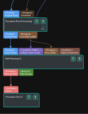
This Step uses the input vision points to plan the robot path and outputs the successfully planned robot path.
|
The Path Planning Step feature is Mech-Viz-related and requires Mech-Viz installation and software licensing to use the Step. |
|
Usage Scenario
This Step is usually used in projects where the Standard Interface or Adapter is used for communication, and only the robot motion path near the vision point needs to be planned. After you build a scene and input the vision points, this Step will output a collision-free robot motion path after point cloud collision detection and path planning.
The common predecessors and successor of this Step are as follows:
-
Predecessors: Steps related to pose adjustment and pose processing.
-
Steps to follow: Set the “Port Type” parameter in the “Output” Step to “Predefined (robot path)”.
Input and Output
Input
-
Vision Points: Poses input to this port will be used for robot path planning.
-
Collision Point Cloud: Point clouds input to this port will be used for collision detection with the tool.
-
Pose Labels: Object labels corresponding to vision points will be input to this port.
-
Object Dimensions: Object dimensions corresponding to vision points will be input to this port.
The following three input ports will appear after the Update Scene Object Settings is enabled.
-
Scene Object Names: This port is the name of the scene object.
-
Scene Object Dimensions: This port is the dimensions of the scene object.
-
Scene Object Poses: This port is the pose of the scene object.
Parameter Description
Path Planning Settings
- Workflow Configuration
-
Description: Open the path planning tool and select the configured workflow in the drop-down list.
- Update Scene Object
-
When this option is enabled, the Scene Object Names, Scene Object Dimensions, and Scene Object Poses input ports will be added for updating the poses and dimensions of scene objects such as the bin.
Usage Scenario
- Select Scenario
-
Description: Select the usage scenario of the current solution.
Value list: Matching, Depalletizing, Others
-
Matching: Applicable to scenarios where target objects are created in the target object editor and their poses are obtained by point cloud model matching.
-
Depalletizing: Suitable for depalletizing scenarios, where target object poses can be obtained directly through deep learning or other methods without point cloud model matching.
-
Others: Applicable to scenarios where target object poses are obtained by other methods than the above two scenarios.
Default value: Matching
-
- Method to Convert Data
-
Description: By selecting the result conversion method, this Step converts the recognition result to the data type needed for picking.
Value list: Generate picking strategy based on object center point, generate picking strategy based on pick points
-
Generate picking strategy based on object center point: Suitable for symmetrical target objects that require orientation adjustment of the object center point.
-
Generate picking strategy based on pick points: Suitable for target objects with multiple pick points that need to be filtered.
Default value: Generate picking strategy based on object center point
-
Collision Detection Settings
- Point Cloud Type
-
Description: This parameter is used to select the type of point cloud that is input to the path planning tool.
Value list: CloudXYZRGB (colored point cloud), CloudXYZ (point cloud), and CloudXYZNormal (point cloud with normals)
Default setting: CloudXYZRGB
- Point Cloud in Camera Frame
-
Description: Please select this parameter when the point cloud is in the camera reference frame. Once this option is selected, the point cloud will be converted to the robot reference frame and sent to the path planning tool. If this option is not selected, the point cloud will be sent to the path planning tool directly.
Default setting: selected.
- Remove Point Cloud of Target Object
-
Description: This parameter is used to remove the point cloud of the part that overlaps with the target object and avoid collisions between the gripper and the part as much as possible.
Default setting: Unselected
- Search Radius of Target Object Point Cloud
-
Description: Take any point in the point cloud of the target object as the center, and the point cloud within the search radius will be removed. Please set this parameter when Remove Point Cloud of Target Object is selected.
Default value: 3 mm
Other Input Settings
- Other inputs
-
Parameter description: Once this option is selected, new input ports “Pick Point Labels”, “Target Object Dimensions”, and “Pick Point Offsets” will be added to the Step.
Default setting: Unselected
Instruction: The new input ports are optional. You can connect the new ports according to the actual requirement.