Fundamentals
Mech-Viz project
Mech-Viz projects refer to the robot path planning projects created in Mech-Viz.
Starting from Mech-Viz 2.0.0, the Mech-Viz project cannot be used independently and must belong to a solution to be utilized for robot path planning and robot movement control. Please refer to Project and Solution to learn more about their operations.
All the configurations of the Mech-Viz project are stored in the folder with the same name as the project.
| “Projects” mentioned in Mech-Viz user manual refer to Mech-Viz projects unless there are special instructions. |
Solution
A solution is a collection of configurations and data for the components, including robot communication, vision processing, and path planning, required to deliver a vision application. A solution can contain several Mech-Vision projects, but at most one Mech-Viz project.
Project Resources
Project resources refer to various fundamental resources used in the project, including the robot, tools, target objects, and scene objects.
Robot |
In Mech-Viz, robots refer to multi-joint robotic arms or the gantry robot for industrial use. |
Tools |
Tools, such as grippers and suction cups, are specially designed mechanical devices attached to the flange of the robot to perform various tasks. |
Target Objects |
Target objects refer to the objects on which the tool performs tasks, such as cartons, metal parts, parts to be glued or welded, etc. |
Scene Objects |
Scene objects, usually including the safety fence, picking bin, tray, camera, camera mounting frame, refer to objects in the real scenarios where the robot performs various tasks. |
Pose
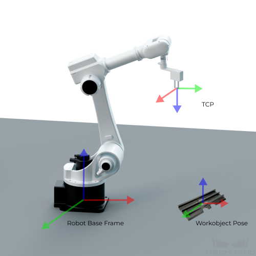
TCP (Tool Center Point)
TCP is the pose of a specific point on the tool or outside the tool relative to the flange at the robot end.
In tasks such as picking target objects, saying that the robot should move to a specific point in space actually means that the TCP should move to that point.
Target Object Pose
Target object pose is the pose of a certain point on the target object relative to the robot base frame. When placing the target object, we usually make the target object pose coincide with a certain target pose.
Target Object Pick Point
There may be several different pick points on one target object, which are output by Mech-Vision. When picking the target object, the robot will move its TCP to the location of the pick point so that the origins and X-axes of these two points coincide with each other, while the directions of their Y-axes and Z-axes are opposite.
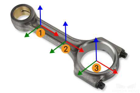
Among them, ① and ② are the pick points of shafts, while ③ is the pick point of ring center.
Robot Pose
The robot pose usually refers to the position and orientation of the robot in the 3D space. It is expressed using the tool pose or joint positions.
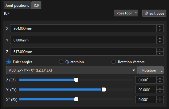
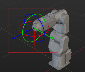
Tool Pose
The tool pose describes the position and orientation of the tool reference frame relative to the robot base reference frame.
The tool pose determines the position (x, y, z) and orientation (usually represented by Euler angles, rotation matrix, and quaternions) of the tool. It focuses on the positional relationship between the tool and the working space, and describes the position and orientation of the tool, such as robotic claw, and welding torch, when the robot performs a task.
-
Euler Angles
Euler Angels are used to describe the rotation of the object in the 3D space.
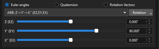
It consists of three angles that correspond to the rotation of each of the three axes. These three axes usually rotate around the X, Y and Z-axis of the object’s fixed reference frame respectively. The same orientation can be expressed in different ways using multiple Euler angles. To avoid ambiguity, a consistent definition of Euler angles is applied in the robots from different brands. For more information on Euler angle conventions and representations, please refer to Euler Angles.


-
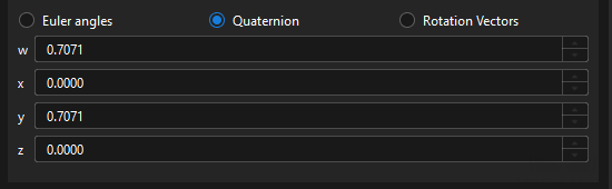
Quaternions
To avoid the gimbal lock problem of using Euler angles, some robot manufacturers use quaternions to represent the orientations in the space. A quaternion roughly refers to using three numbers to define the a spatial rotation axis and using the fourth number to define the rotation angle. The tool reference frame can reach the target pose from its initial state by rotating the angle around the spatial rotation axis.
-
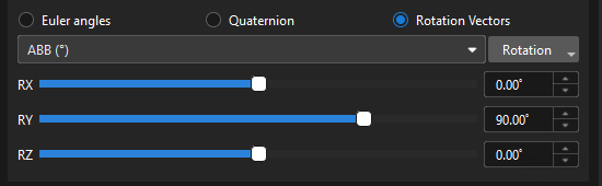
Rotation Vector
The rotation vector, also known as the axial angle, is used to describe the rotation state of the tool.
Currently, it is only used by UR robots.
Joint Positions
Joint positions refer to the rotation angles of each joint of the robot relative to its initial position or reference position. This description can represent the state of each joint in line with the hardware structure of the robot.
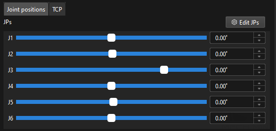
The joint positions are mapped to the tool pose by forward kinematics computation, while the tool pose is mapped to the joint positions by inverse kinematic computation.
Flange Pose
The flange pose is the pose of the robot flange frame relative to the robot reference frame, whose representation is the same as that of the tool pose. It can be seen as a special tool pose that the TCP is at the center of the flange without any rotation.
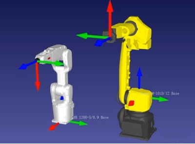
The default orientation of the flange reference frame defined by each robot manufacturer is different, resulting in different default angles for the flange pose. For example, the default X-axis orientation for ABB robots is downward, while that for FANUC robots is upward. In addition, most robots have a flange pose with the Z-axis perpendicular to the flange surface facing outward, but for the TURIN robots, it is the X-axis that is perpendicular to the flange surface facing outward.
Motion Type
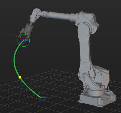
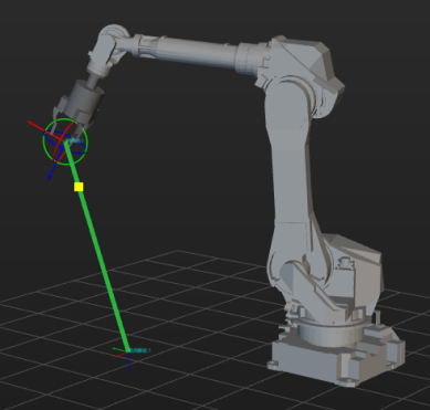
Robot motion usually refers to the process of moving the robot tool center point (TCP) from point A to point B in space. The joint motion and linear motion are two fundamental methods of robot motion.
Rotational Symmetry and Picking Relaxation
Rotational Symmetry of the Tool
A rotational symmetric tool will coincide with itself after rotating around its axis of symmetry.
Please refer to Rotational Symmetry of the Tool for detailed description.
Rotational Symmetry of the Target Object
A rotational symmetric target object will coincide with itself after rotating around its axis of symmetry.
Please refer to Rotational Symmetry for detailed description.
Picking Relaxation of the Target Object
When the robot picks certain target objects, the picking pose of the robot is allowed to be changed flexibly within a specific angle range, which is the picking relaxation.
Please refer to Picking Relaxation for detailed description.