Set the Pick Points by Jogging the Robot, and Generate the Point Cloud Model Based on the Acquired Point Cloud
In this workflow, you can add the pick point to the target object by robot teaching, and then acquire the point cloud to generate the point cloud model and create the target object. This workflow is suitable for scenarios requiring high picking accuracy or where robots or other devices have significant errors.
In the homepage of the target object editor, click Select under the Jog robot and get point cloud workflow, and set the target object name to enter the configuration process. The overall configuration process is shown in the figure below.

-
Teach the pick point: Add the pick point to the target object by the robot teaching method.
-
Acquire the point cloud: Use the current project to acquire the point cloud. Then adjust the parameters and set the 3D ROI to generate a point cloud model.
-
Edit model: Edit the generated point cloud model, including the configurations for the point cloud display and the calibration of the object center point, to ensure better performance of the matching task.
-
Set collision model (optional): Generate the collision model for collision detection during path planning.
The following sections provide detailed instructions on the configuration.
Teach the Pick Point
-
Place the target object within the camera’s field of view and ensure that the robot can pick the target object properly.
-
Use the teach pendant to control the robot to accurately reach the expected pick point of the target object.
-
It is recommended to set the robot TCP near the center of the point cloud model to reduce picking errors.
-
Record and enter the robot flange pose and TCP at the pick point in the parameter configuration section on the right.
-
Use the teach pendant to control the robot to move away from the pick point, ensuring that the position of the target object remains unchanged during the departure process.
-
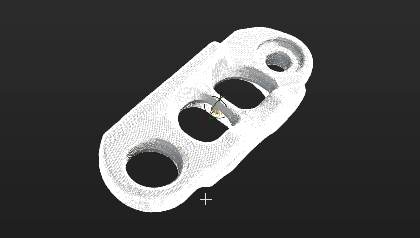
Collect the point cloud of the target object and create a point cloud model.
|
After adding the pick point by jogging the robot, all tools configured in Mech-Viz or the path planning tool will be enabled by default, and the picking configuration is not required. |
Acquire Point Cloud
Set Project Information
Select the “Capture Images from Camera” Step in the current project to acquire the point cloud. Click Acquire point cloud, and then the result can be viewed in the visualization area.
Configure Point Cloud Display Settings
By configuring Point cloud display settings, you can view different types of point cloud models, i.e., the models of all point clouds, surface point cloud only, and edge point cloud only, for the current target object and edit the point cloud model according to actual requirements. You can also change the display color of the point cloud model and view relevant reference information, such as the pseudo-textured point cloud.
Preprocess Parameters
For detailed explanations of the parameters, refer to Preprocessing Parameters.
|
If the “3D Target Object Recognition” Step is used in the project, you can enable Use parameters of Step “3D Target Object Recognition”, and then the parameter values in the “3D Target Object Recognition” Step will be synchronized. |
Set ROI and Background
By selecting a 3D ROI or capturing an image of the background, you can quickly remove irrelevant point clouds from the scene, enabling rapid extraction of the target object’ point cloud.
If you need to remove the background by capturing the image of the background, you must move the target object out of the camera’s view after acquiring the point cloud. Then click Capture and remove background, and the tool will automatically capture an image of the background and remove the point cloud of the background.
Now the point cloud acquisition has completed. You can click Next to start editing the generated point cloud model.
Edit Point Cloud Model
The generated point cloud model should be edited for better performance in the subsequent matching task.
Configure Point Cloud Display Settings
By configuring Point cloud display settings, you can view different types of point cloud models, i.e., the models of all point clouds, surface point cloud only, and edge point cloud only, for the current target object and edit the point cloud model according to actual requirements. You can also change the display color of the point cloud model and view relevant reference information, such as that of the pseudo-textured point cloud.
Calibrate Object Center Point
The tool can automatically calculate the object center point. If you need to calibrate the object center point, select the calculating method under Calibrate center point by application, and click Start calculating.
| Method | Introduction | Operation |
|---|---|---|
Re-calculate by using original center point |
The default calculation method. Calculate the object center point according to the original object center point and features of the target object. |
|
Calibrate to center of symmetry |
Calculate the object center point according to the object’s symmetry.
|
|
Calibrate to center of feature |
Calculate the object center point according to the selected Feature type and the set 3D ROI. |
|
Configure Point Cloud Model
To better use the point cloud model in the subsequent matching task and enhance matching accuracy, the tool provides the following two options for configuring the point cloud model. You can enable the Configure point cloud model switch as needed.
Avoid False Matches
Once Avoid false matches is enabled, more matching attempts will be made based on the settings to obtain matching results with higher confidence. However, more matching attempts will lead to longer processing time.
Two methods to avoid false matches are offered, i.e., Auto-calculate unlikely poses and Configure symmetry manually. See the table below for more information.
| Method | Introduction | Operation |
|---|---|---|
Auto-calculate unlikely poses |
Poses that may cause false matches will be calculated automatically. In subsequent matches, poses that successfully match these poses will be considered unqualified and filtered out. |
|
Configure symmetry manually |
For rotationally symmetric target objects, configuring the rotational symmetry of the point cloud model can prevent the robot’s end tool from unnecessary rotations when it is holding the target object. This increases the success rate of path planning and reduces the time required for path planning, allowing the robot to move more smoothly and swiftly. |
Select the symmetry axis by referring to Rotational Symmetry of Target Objects, and then set the Order of symmetry and Angle range. |
|
When Auto-calculate unlikely poses is selected, for the option to take effect in the subsequent matching, you need to configure the relevant parameters in the used matching Steps. See the following for details.
|
Set Weight Template
In the target object recognition process, setting a weight template can enhance the accuracy of matching results by emphasizing the selected features for recognition. Weight templates are typically used to distinguish the orientation of the target object, and the set weight template will affect the matching results. The procedures to set a weight template are as follows.
|
A weight template can only be set when the Point cloud display settings is set to Display surface point cloud only. |
-
Click Edit template.
-
In the visualization area, hold and press the right mouse button to select a part of the features on the target object. The selected part, i.e., the weight template, will be assigned more weight in the matching process.
By holding Shift and the right mouse button together, you can set multiple weighted areas in a single point cloud model.
-
Click Apply to complete setting the weight template.
|
For the configured weight template to take effect in the subsequent matching, go to the “Model Settings” parameter of the “3D Matching” Step, and select the model with properly set weight template. Then, go to “Pose Filtering” and turn on the switch Consider Weight in Result Verification. The “Consider Weight in Result Verification” parameter will appear after the “Parameter Tuning Level” is set to Expert. |
Now you can click Save to save the configurations for the target object. To set the collision model, click Next.
Set Collision Model (Optional)
The collision model is a 3D virtual object used in collision detection for path planning. You can configure the following settings on the collision model according to the actual situation.
Select Collision Model Generating Mode
The tool automatically recommends the collision model generating mode based on the current configuration workflow. The recommended mode for this case is Use STL model to generate point cloud cube. This tool will generate the point cloud cube based on the imported STL model and conduct collision detection. The collision model generated in this method features high accuracy, while the collision detection speed is lower.
Select STL Model
Click Select STL model and then select the STL model used to generate the point cloud cube.
Configure Point Cloud Cubes
Point cloud cubes are the cubes centered at each point in the point cloud. If these cubes collide with other objects, the point cloud is considered to have collided with these objects.
To perform collision detection, the point cloud is filled with cubes with an edge length of 2 mm. When the target object is too small and its dimensions are close to the edge length of the point cloud cube, the accuracy of the collision model will decrease. When the target object is too large and the collision model includes too many point cloud cubes, the collision detection speed will slow down.
Align Models
Aligning the collision model with the point cloud model of the target object ensures effective collision detection. You can click Auto-align point cloud model and collision model or manually adjust the pose of the collision model to achieve the alignment with the point cloud model of the target object.
Configure Symmetry of Held Target Object
Refer to Rotational Symmetry of Target Objects to select the axis of symmetry, and then set the Order of symmetry and Angle range.
Now, the collision model settings are completed. Click Save to save the target object to Solution folder\resource\workobject_library. Then the target object can be used in subsequent matching Steps.