Automatic Calibration in the Eye-in-Hand Setup (Four-Axis/Five-Axis Robot)
This how-to guide introduces how to complete the automatic calibration for four-axis/five-axis robots in the eye-in-hand (EIH) setup.
Introduction to the Overall Process
The following figure shows the overall process of the automatic calibration for a four-axis/five-axis robot in the eye-in-hand (EIH) setup.

-
Preparation before Calibration: You finish the required preparations before the calibration.
-
Configuration before Calibration: You finish the pre-calibration configuration, such as selecting the robot model, and the camera setup.
-
Perform Calibration: You start the calibration and obtain the calibration result after several calibration steps. In this step, you need to perform operations on the robot side to establish the communication between the vision system and the robot.
-
Validate Calibration Result: You validate the obtained calibration result to check whether the result meets the requirements.
-
Apply Calibration Result: You use the new calibration parameter group in the vision project.
The following sections introduce the process in detail.
Preparation before Calibration
Before hand-eye calibration, you need to finish the following preparations:
Construct the Vision System
Construct the Mech-Mind Vision System by referring to the section Vision System Hardware Setup.
You need to use Mech-Eye Viewer, and Mech-Vision&Mech-Viz during hand-eye calibration. Please ensure that they have been installed and are running the latest versions.
Complete the Robot Communication Configuration
If the robot uses the Standard Interface to communicate with the Vision System, please set up the Standard Interface communication with the robot. According to the robot brand used in your project, you can complete the Standard Interface communication configuration by referring to the “Set up Standard Interface Communication” guide for the corresponding robot brand in Standard Interface Communication.
If the robot uses the Master-Control to communicate with the Vision System, please set up the Master-Control communication with the robot. According to the robot brand used in your project, you can complete the Master-Control communication configuration by referring to the “Set up Master-Control Communication” guide for the corresponding robot brand in Master-Control Communication.
Prepare the Materials Required for Calibration
The automatic calibration in the EIH setup needs to use the calibration board.
Please prepare the calibration board according to the following requirements:
-
Ensure that the circles of the calibration board are clearly visible and without obvious scratches, and the board does not suffer from deformations.
-
In the EIH setup, please place the calibration board in the center of the working plane, where target objects are to be placed.
Check the Point Cloud Quality of the Calibration Board
| The point cloud quality of the calibration board will affect the accuracy of hand-eye calibration. Check the point cloud quality of the calibration board to ensure the accuracy and reliability of the calibration results. The calibration process includes the step of checking the point cloud quality of the calibration board. You can also check the point cloud quality of the calibration board before starting the calibration to save time. |
-
Place the calibration board horizontally at the center of the working plane within the camera’s field of view.
-
Open the Mech-Eye Viewer software, select the camera used by the project, and then select the “calib” parameter group and adjust camera parameters.
-
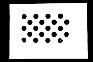
Adjust the 2D parameters to ensure that the overall 2D image is not too dark, and each calibration circle is clearly visible.
-
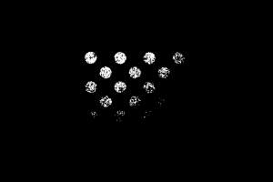
Adjust the 3D parameters to ensure that each calibration circle on the calibration board is complete and visible.
If the on-site ambient lights are not ideal and affect the quality of 2D images and point clouds, you can use shading or supplemental light to improve the lighting conditions.
-
Make sure that the point cloud quality of the calibration board is up to standard after completing the preceding steps.
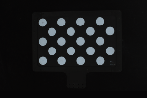
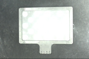
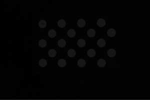
Normal Overexposed Underexposed 2D image
Point cloud
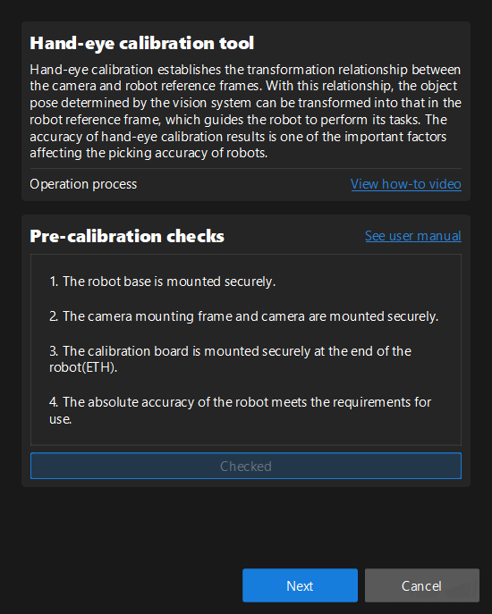
Complete Pre-calibration Checks
Please refer to Pre-calibration Checks and complete the following checks:
-
Confirm that the robot base is mounted securely.
-
Confirm that the camera mounting frame and camera are mounted securely.
-
Confirm that the absolute accuracy of the robot meets the requirements for use.
-
Verify robot model parameters.
-
Confirm that the camera is warmed up.
Configuration before Calibration
-
Open Mech-Vision, and click the Camera Calibration button in the toolbar. The Configuration before Calibration window will be prompted.
-
After confirming that pre-calibration checks are completed, click I’ve finished all checks, and then click Next.
-
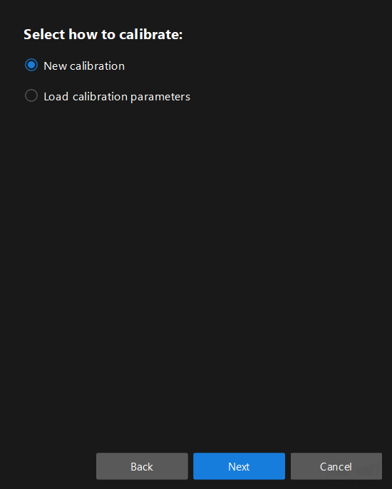
In the Select how to calibrate window, select the New calibration radio button, and then click the Next button.
-
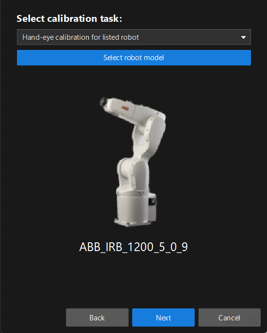
In the Select calibration task window, select Hand-eye calibration for listed robot from the drop-down list box, click the Select robot model button to select the robot model used by the project, and then click the Next button.
-
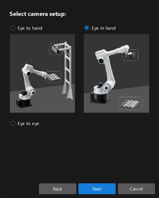
In the Select camera setup window, select the Eye in hand radio button, and then click the Next button.
-
In the Calibration method and robot control window, select Automatic and Standard Interface, and then click the Calibrate button. The Calibration (Eye in Hand) window will be prompted.
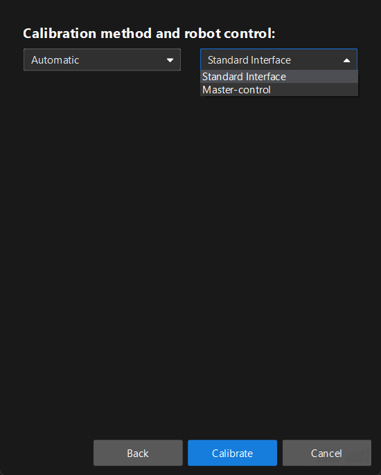
If the Master-Control is used to communicate with the robot, then select Automatic and Master-control.
Till now, you have completed the pre-calibration configuration and can start the calibration procedure.
Perform Calibration
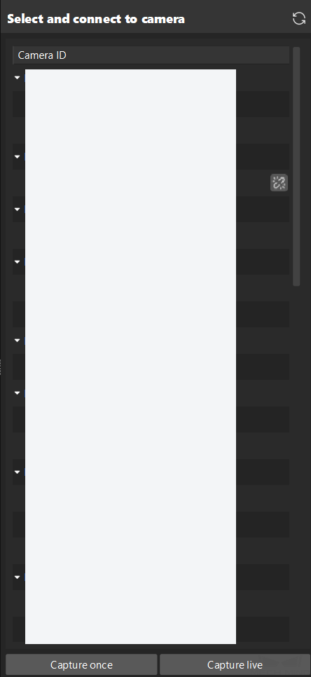
Connect to Camera
-
In the Connect to camera step, select the camera to connect in the Camera ID list, and then click the
 button or double-click the camera entry to connect to it.
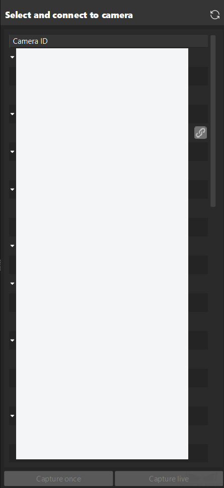
-
After the camera is connected, click the Capture live or Capture once button.
-
In the right Image viewer panel, ensure that the camera can capture images normally and click the Next button on the bottom bar.
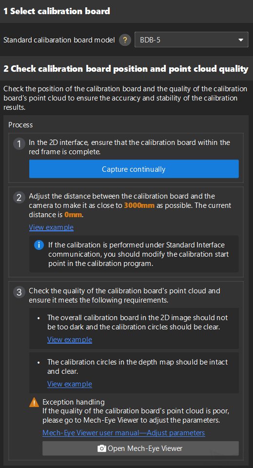
Mount Calibration Board & Check Intrinsic Parameters
-
In the Mount calibration board & check intrinsic parameters step, set the Standard calibration board model parameter in the 1 Select calibration board area.
-
In the 2 Check calibration board position and point cloud quality area, read carefully the requirements on the calibration board position and point cloud quality, and then click the Capture continually button. The Capture continually button will turn into Stop capturing and detect position.
-
Manually control the robot carrying the calibration board to move to an appropriate position, ensuring the calibration board is fully within the red frame, and the distance between the calibration board and the camera is as close to the recommended value on the interface as possible.
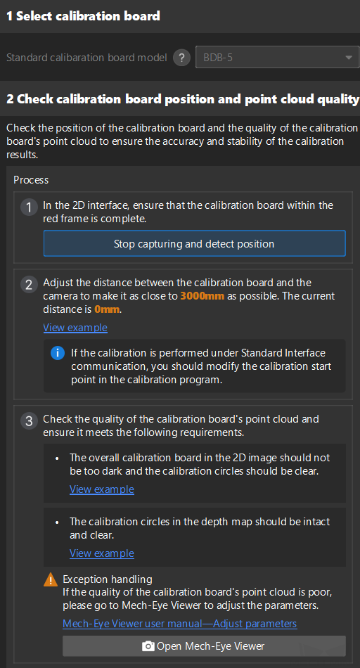
If the Standard Interface communication mode is used for calibration, after adjusting the distance between the calibration board and the camera according to the prompts on the interface, the robot’s position can be used as the starting point for calibration. -
Please ensure that the 2D image and depth map of the calibration board meet the requirements, and then click the Stop capturing and detect position button.
If the captured images do not meet the requirements, click Open Mech-Eye Viewer button to open the Mech-Eye Viewer software, adjust the 2D and 3D exposure parameters and re-capture images. Please note that you need to change the Parameter group parameter to “calib” first.
-
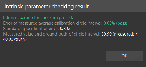
In the 3 Check intrinsic parameters area, click the Check intrinsic parameters button.
-
Confirm the results of the camera intrinsic parameter check.
-
If the camera intrinsic parameter check passes, click the OK button in the prompted window, and then click the Next button on the bottom bar.
-
If the intrinsic parameter check fails, you can draw aid circles to assist in the intrinsic parameter check, and then click the Recheck intrinsic parameters button.
-
Draw an Aid Circle
-
To draw an aid circle, click the Draw an aid circle button.
-
In the right Image viewer panel, right-click the calibration board image, clear the Fit to window checkbox, press the Ctrl key and drag the roller to adjust the image to a suitable size.
-
Move the mouse pointer to the cross center point of the calibration circle, press the left mouse button and make the aid circle completely include the calibration circle and then release the left mouse button.

-
Click the Recheck intrinsic parameters button, and confirm that the camera intrinsic parameter check passes. If the intrinsic parameter check still fails, please contact Technical Support.
Connect the Robot
If the Standard Interface communication is used during calibration, please refer to Connect the Robot (Standard Interface).
If the Master-Control communication is used during calibration, please refer to Connect the Robot (Master-Control).
Connect the Robot (Standard Interface)
-
(Optional) In the Connect the robot step, click the Start interface service button. The button will turn into Waiting for the robot to connect.... If the Standard Interface Communication option on the toolbar was previously enabled, this step is not necessary.
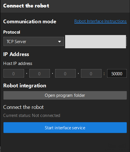
-
On the robot teach pendant, perform several operations: Select the automatic calibration program, teach the start point and run the program. After the program is started, the log message “Entering the calibration process, please start the calibration in Mech-Vision” will be printed in the Console log panel.
According to the robot brand used in your project, you can complete the operations on the robot side by referring to the “Automatic Calibration” guide for the corresponding robot brand in Standard Interface Communication.
Connect the Robot (Master-Control)
-
On the robot teach pendant, select and run the Master-control program.
According to the robot brand used in your project, you can complete the operations on the robot side by referring to the “Set up Master-Control Communication” guide for the corresponding robot brand in Master-Control Communication.
-
In the Connect the robot step, set the Robot IP address parameter.
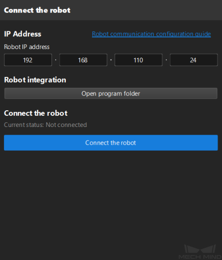
-
Click the Connect the robot button in the Connect the robot area. The button will turn into Waiting for the robot to connect...
-
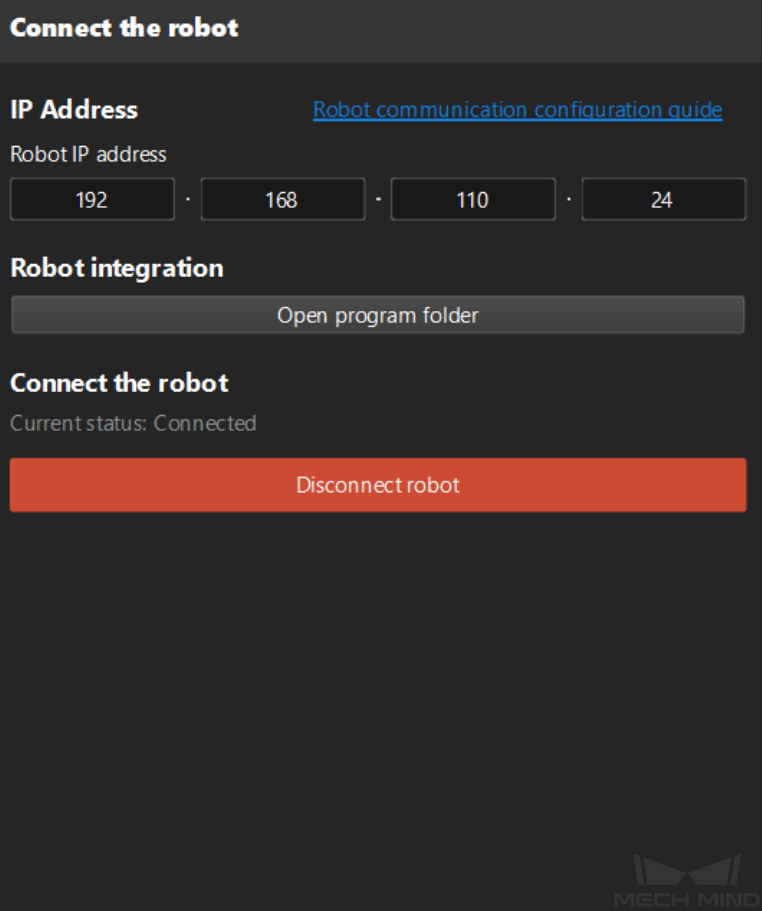
Wait until the “Disconnect robot” status message is displayed in the Connect the robot area, and then click the Next button.
Set Motion Path
-
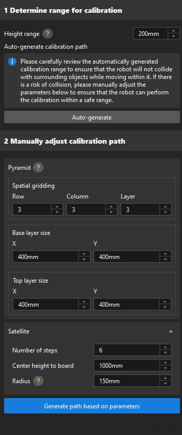
Determine the calibration range.
Set the Height range parameter. The Height range parameter should be set according to the recommended working distance range of the camera and the size of the robot’s working space. Generally, the height range is slightly larger than the height of the target object(s) to be recognized.
-
Automatically generate the calibration path (recommended).
Click the Auto-generate button, and click the OK button in the prompted window Auto align robot path to camera frame.
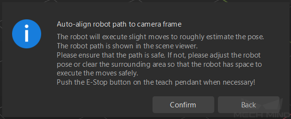
This operation will slightly move the robot and capture images. The whole process may take 10 to 15 seconds. Please ensure that the motion path is safe. In case of emergency, please tap the emergency stop button on the robot teach pendant to stop the robot immediately. After the calibration path is generated, click OK in the pop-up Calibration window.
-
Modify the calibration path manually.
If the calibration path automatically generated in step 2 has a collision risk, you can also manually modify the calibration path by modifying the pyramid structure, re-dividing the pyramid grid, and setting the rotation angle.
-
Spatial gridding: To shorten the calibration time or if the calibration range is small, you can set two rows, two columns, and two layers.
-
Base layer size: If the space on site is sufficient, the base layer size is generally the size of the bin or pallet. If site space is limited, the base layer size can be appropriately reduced to avoid collisions.
-
Top layer size: Typically, the top layer size should be slightly smaller than the base layer size, making the calibration range a trapezoidal.
-
-
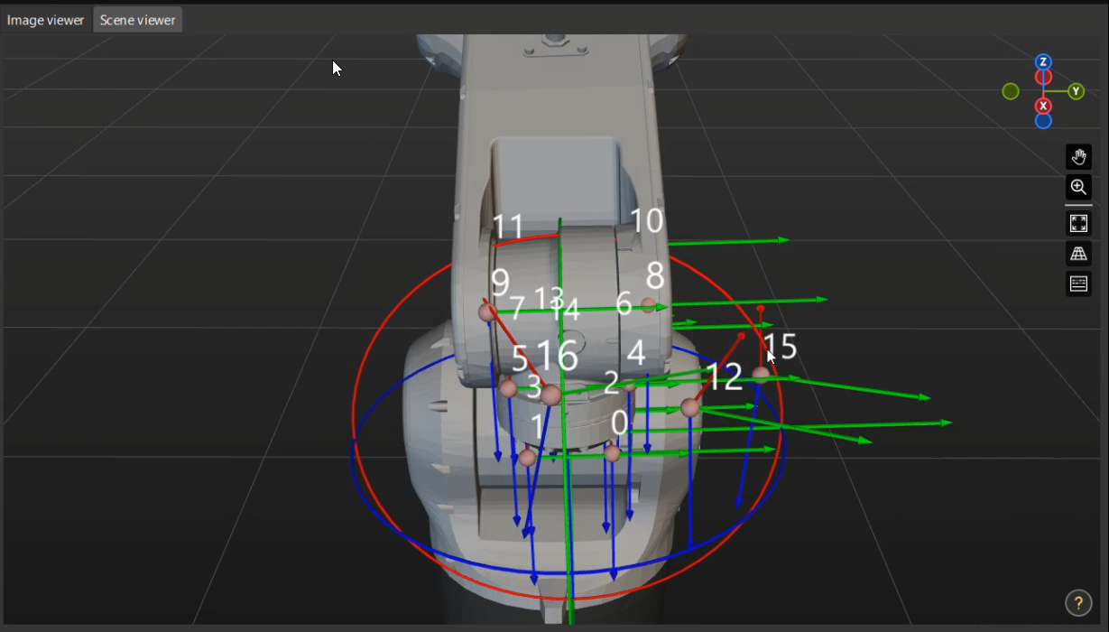
In the right Scene Viewer panel, make sure that all the waypoints are at a proper position and that the robot will not collide with surrounding objects when moving.
-
Click the Generate motion path based on path parameters button and then click the Next button on the bottom bar.
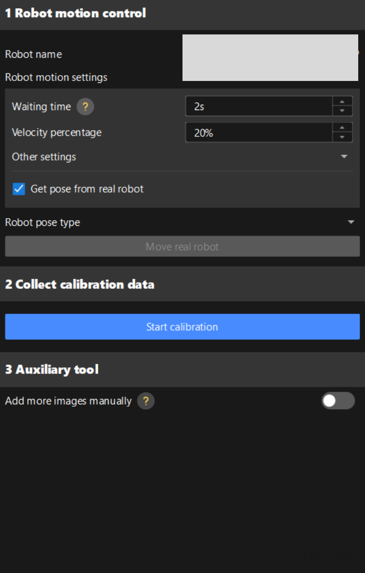
Obtain Images and Poses
| Before this step, please make sure that the current robot pose matches the real pose on the robot teach pendant. |
-
In the Obtain Images and Poses step, click the Start calibration button.
-
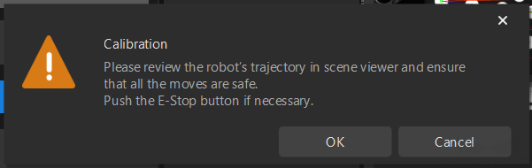
Read the safety window carefully and click the OK button.
-
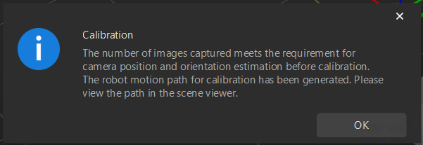
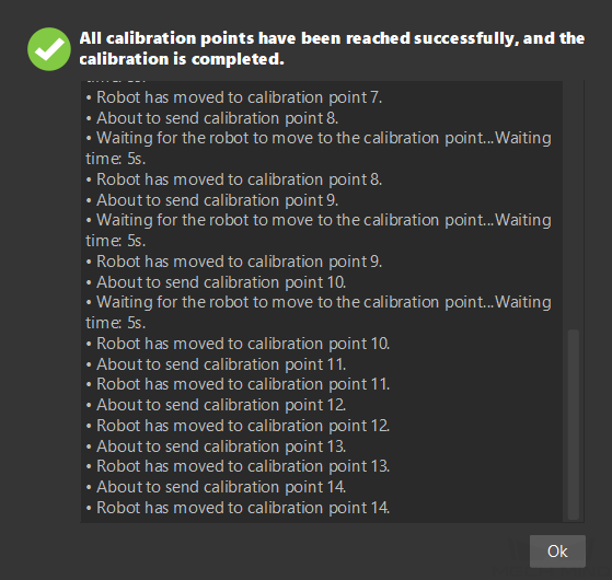
Wait until the robot finishes moving along the preset path and the camera finishes capturing images on all waypoints. A pop-up window will display the progress of moving to the calibration point.
Please stay away from the robot working area to keep safe. -
When the pop-up window says “All calibration points have been reached successfully, and the calibration is completed.”, click the Ok button.
-
Confirm that the collected calibration data meets the data requirements, and then click the Next button on the bottom bar.
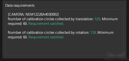
If the requirements are not met, please manually move the robot (through the teach pendant or Mech-Viz), enable the Add more images manually option in the 3 Auxiliary tool, and click the Add images and record flange poses button to add the calibration board image and enter the robot flange pose.
Calculate Extrinsic Parameters
-
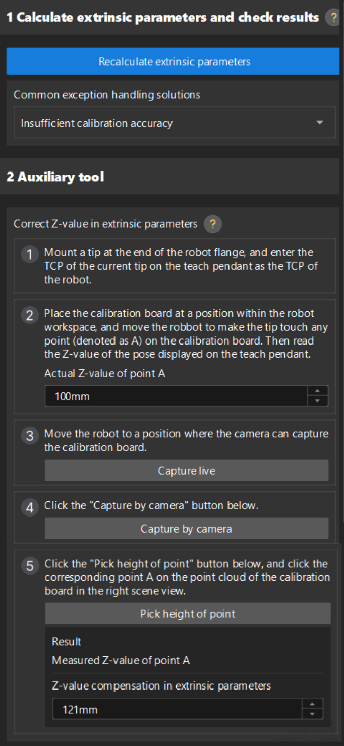
In the Calculate extrinsic parameters step, click the Calculate extrinsic parameters button in the 1 Calculate extrinsic parameters and check results area.
-
In the prompted window indicating calibration success, click the OK button.
-
Follow the instructions on correcting the Z-value in extrinsic parameters in the 2 Auxiliary tool area to calculate the Z-value compensation in extrinsic parameters.
Due to the lack of degrees of freedom in rotation in four-axis/five-axis robots, the captured images during calibration may lack the rotation. After calibration, you need to correct the Z-value in extrinsic parameters. -
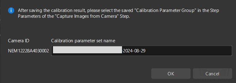
Click the Save button on the bottom bar. In the prompted Save Calibration Files dialog box, click the OK button. The camera calibration result will be automatically saved in the “calibration” directory of the project.
Till now, the calibration process is completed.
Validate Calibration Results
This section provides methods for quickly validating calibration results.
View Error Point Cloud in Point Cloud Viewer
After calculating the camera extrinsic parameters, please perform the following operation:
-
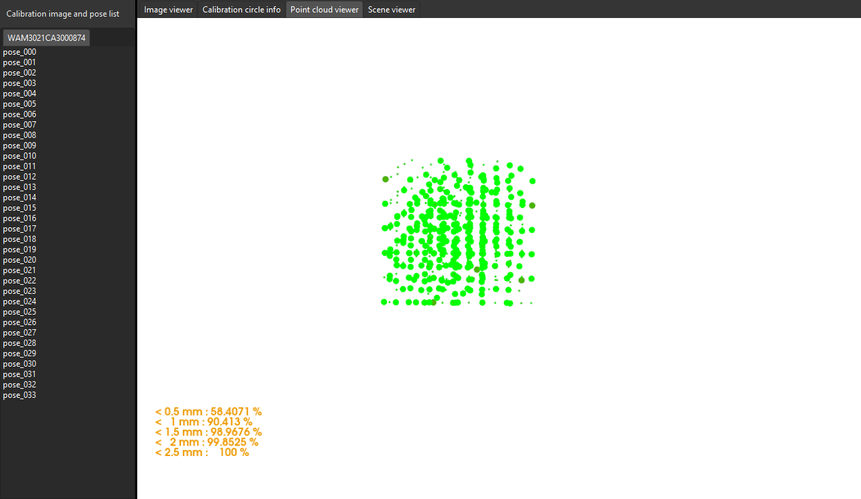
In the Calculate extrinsic parameters step, view the error point cloud in the right Point cloud viewer panel after the calibration calculation is complete.
The error point cloud shows the deviation between the calculated value and the actual value of the circles on the calibration board at each calibration point. For the detailed description, please refer to Error Point Cloud Description. -
Confirm that the calibration accuracy error meets the project’s requirements. Find the error value with the 100% percentage to get the rough calibration accuracy.
For example, the point cloud view after calibration using multiple random calibration board poses is shown in the figure below. The calibration error is within ±2.5 mm.
Roughly Check Coincidence Degree between the Point Cloud of the Robot and the Robot Model in Scene Viewer
After calculating the camera extrinsic parameters, please perform the following operation:
-
Move the robot end effector to a position where the camera can capture images of the base.
-
In the Calculate extrinsic parameters step, click the Capture by camera button in the 2 Auxiliary tool area. This operation triggers the camera to capture images.
-
In the right Scene viewer panel, visually check coincidence degree between the point cloud of the real robot and the robot model. If the point cloud of the robot roughly coincides with the robot model, the calibration is successful.
As shown in the figure, the color part is the robot model, the black part is the robot point cloud. From the figure, you can learn that the robot model and the robot point cloud roughly coincides. This indicates that the calibration result can be used.
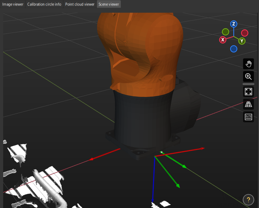
| If the camera cannot capture images of the base due to robot degrees of freedom or workspace limitations, you can choose to view the offset of the calibration board’s point cloud relative to a fixed point in the scene viewer instead. |
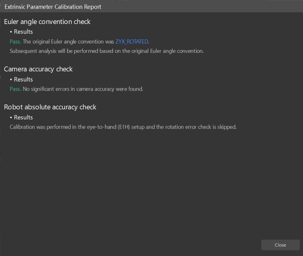
Use the Extrinsic Parameter Accuracy Validation Tool to Validate Extrinsic Parameters
For high-precision scenarios (within ±2mm), this method should be used to thoroughly validate the extrinsic parameters.
In the Calculate extrinsic parameters step, click Extrinsic parameter accuracy to open the tool. Please refer to the tool’s guidance to validate the extrinsic parameter accuracy and generate the final evaluation report.
If the calibration accuracy does not meet the requirements, you can click the Check report on extrinsic parameter calibration button to view the results of Euler angle convention check, camera accuracy check, and robot absolute accuracy check.
|
Apply Calibration Result
The calibration parameter group includes the intrinsic parameter and extrinsic parameter files of the camera. If you have used the camera’s calibration parameter group in the Mech-Vision project, you need to select the new calibration parameter group in the Mech-Vision project after hand-eye calibration.
-
Select the Capture Images from Camera Step.
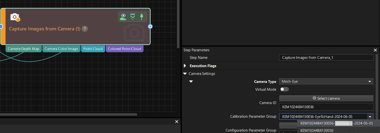
-
In the Step Parameters panel, click
 of the Calibration Parameter Group parameter, and select the new calibration parameter group.
Calibration-Related Status Codes
If the robot uses the Standard Interface to communicate with the Vision System during hand-eye calibration, the Vision System will return status codes in response data to indicate the execution status of the commands. The status codes indicate both the normal execution results and execution failures. You can perform further troubleshooting according to the status codes.