Capture Images from Camera
Function
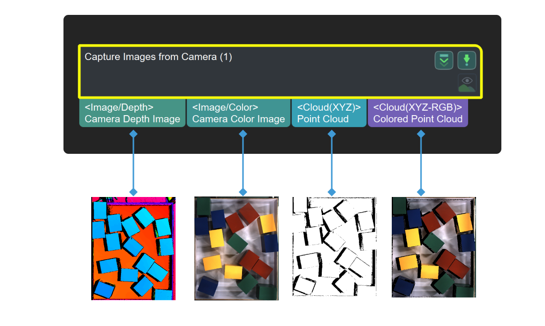
This Step is used to obtain color images, depth maps, and point clouds from a real or virtual camera.
|
When this Step is used to connect a DEEP (V4) or LSR (V4) series camera, and the 2D Image Type is set to Internal IR Image, the output “color image” is actually a 2D image (Depth Source). If you want to adjust the 2D image (Depth Source), adjust the 2D Image (Depth Source) Exposure Time of the 2D Image (Depth Source) Exposure Mode in Mech-Eye Viewer. |
Usage Scenario
Used as the initial input entry of a Mech-Vision project, this Step collects data from a Mech-Eye Industrial 3D Camera or third-party camera or acts as a virtual camera for inputting simulated data source.
Input and Output
|
By default, the textured point cloud output by the “Capture Images from Camera” Step is used as the scene point cloud in the project. If the default scene point cloud is used in the project, you can capture images even if the “Capture Images from Camera” Step is not connected to a subsequent Step. |
Parameter Tuning
Camera Settings
- Camera Type
-
Description: This parameter is used to select the type of camera in use.
Value list: Mech-Eye
Default value:Mech-Eye Industrial 3D Camera.
Use a Real Camera
- Camera ID
-
Description: This parameter is used to connect the camera and select the calibration parameter group.
Instructions:
-
Click Select camera to open the Choose the camera and parameter group to use window.
-
Select the camera you want to connect and click
 .
.If the camera is connected successfully,
will become  .
. -
After the camera is connected successfully, you can click Select from and select the camera calibration parameter group in the drop-down list and then click OK in the lower right corner of the window.
Once the calibration parameter group is selected successfully, the Camera ID, Calibration Parameter Group, IP Address, and Port parameters will be automatically filled.
-
- Calibration Parameter Group
-
Description: This parameter is used to specify the calibration parameter group of the camera.
- IP Address
-
Description: This parameter is used to display the IP address of the camera. Please do not modify the IP address, otherwise the camera will be disconnected.
- Timeout
-
Description: This parameter is used to set the maximum response timeout period (in seconds) from the camera receives the data to it sends the data to the client. There are two types of timeout:
-
The camera fails to be connected successfully within the set time.
-
The camera fails to capture any images within the set time.
Default value: 10000 ms
-
- Num of Reconnection Attempts
-
Description: This parameter is used to specify the maximum number of attempts to reconnect the camera if the camera fails to be connected within the timeout period.
Default value: 3
- Configuration Parameter Group
-
Description: This parameter is used to select the configuration parameter group of the camera. The camera will capture the data according to the parameters in this parameter group.
|
You can manage parameter groups in Mech-Eye Viewer. |
- Camera Model
-
Description: This parameter is only used to display the model of the currently connected camera.
- 2D Image Type
-
Description: This parameter is used to set the 2D image type output by the camera.
Value list:
-
Internal IR Image: Default value. 2D images (depth source) whose reference frame is the same as that of the depth map and does not need to be rectified.
-
External Color Image: 2D images (texture) that should be rectified before use. You should select Rectify to Depth Map when 2D images of this type are output.
This parameter is only available when a DEEP (V4) or LSR (V4) series camera is used.
-
- Rectify to Depth Map
-
Description: This parameter is used to rectify the reference frame of the external color image captured by a texture camera to the reference frame of the depth map. It can be adjusted only when the 2D Image Type is set to External Color Image for LSR (V4) and DEEP (V4) series cameras.
Default value: Selected.
Tuning instructions:
-
Select this parameter when the point cloud quality is good, and the Calc Color Image for Highest Layer Procedure is used to obtain the corresponding 2D image in the project.
-
If you use the Get Highest Layer Clouds Step followed by the Project 3D Point Cloud to 2D Image Step to obtain the corresponding 2D image, do not select this parameter.
-
To recognize highly reflective workpieces with missing regions in the depth map, deep learning should be used and this parameter does not need to be selected. If this parameter is selected mistakenly under this circumstance, part of the features in the 2D image will be lost, thus affecting the recognition performance of deep learning.
Example: The 2D images before and after the rectification are shown in the figure below. As can be seen from the figure, some of the features of the rectified 2D image are missing, which is due to the presence of missing regions in the depth map.

-
- Max Capture Attempts
-
Description: This parameter is used to specify the total number of attempts to capture the image if the camera fails to capture any image within the timeout period.
Default value: 3
Recommended value: 3
- Robot Service Name in Mech-Center
-
Description: This parameter is used to specify the robot service name, which should be the same as the name of the robot connected in.
Default value: Null.
Use a Virtual Camera
During the actual execution of the project, it may be difficult to reproduce the problem directly. In such cases, enabling the virtual mode can load the saved data to reproduce the problem, which facilitates troubleshooting.
When the Virtual Mode is enabled, you will need to adjust the following parameters.
- Calibration Parameter Group
-
Instruction: Once the Data Path is selected, Calibration Parameter Group will be automatically filled. If there are multiple sets of calibration parameter groups under the Data Path, please select the one you need in the drop-down list.
- Data Path
-
Description: This parameter is used to select the folder where images, intrinsic parameters, and extrinsic parameters are stored.
Instruction: Click the
 icon on the right and select the folder where images, intrinsic parameters, and extrinsic parameters are stored.
|
In the virtual mode, the naming conventions for the images as follows should be followed. The serial number of the color image should be the same as its depth map counterpart.
If the camera mounting method is Eye-in-Hand, note that the serial number of images should correspond to that of flange poses. |
|
In general, it is recommended to set the “Data Path” as a relative path to avoid it being affected by changes in the project folder path. |
Virtual Camera Assistant:
-
If any one of the following descriptions is true when you select the data path, a Virtual Camera Assistant will be triggered to help you select the image data.
-
You have not entered a path in the Data Path box.
-
There are multiple sets of data in the selected folder.
-
There is no color image, depth map, or intrinsic and extrinsic parameters in the selected folder.
-
-
Please follow the steps below to configure in Virtual Camera Assistant:
-
In the Virtual Camera Assistant window, click
 to select the data path.
Once the path is entered successfully, the Camera ID and Parameter group will be automatically filled.
-
Click Verify, and a Camera parameter group updated message will appear.
-
Click
to select the folders where color images, depth maps, and the flange pose are stored one by one. Then, click Confirm after selecting the data.
-
|
The flange pose is needed only when the camera is mounted in the eye-in-hand mode. |
-
Lastly, click OK in the pop-up Setup Complete window.
|
In the virtual mode, please re-select the data path if there is any modification of the image in the selected data path, or else the new image data cannot be read. |
- Play Back Mode
-
Description: This parameter is used to specify the order to read the images.
Value list:
-
Sequential (default value): Read the images in the order of the images in the folder.
-
Repeat One: Read the current image repeatedly.
-
Repeat All: Read all images in the order of the images in the folder, and then read them from the beginning after all images are read.
-
Random: Read images randomly.
Tuning recommendation: Please select the mode according to image reading order you need.
-
- Current Frame Name
-
Description: This parameter is used to display the serial number and timestamp of the currently read image.
- Image Name Type
-
Description: This parameter is used to select the type of image name output by the Color Image Path port.
Value list: Complete Path, File Name, and Base Name.
Default value: Complete Path.
FAQs
-
Image Data Not Found in Virtual Mode of Step “Capture Images from Camera”
-
Changes Ineffective for Parameter “Play Back Mode” of Step “Capture Images from Camera”
-
Incorrect Camera Model Displayed in Step “Capture Images from Camera”
-
Step “Capture Images from Camera” Failed to Acquire Depth Map or 2D Image
-
Step “Capture Images from Camera” Could Not Load Calibration Parameter Group
-
Step “Capture Images from Camera” Could Not Load Configuration Parameter Group