Explanation of the Calibration for Gantry Robots
Related Concepts
Gantry Robot
The gantry robot (also called gantry robot) is an automation device that can realize automatic control. It is reprogrammable based on the XYZ Cartesian coordinate system in space, has multiple degrees of freedom, and is suitable for different tasks.
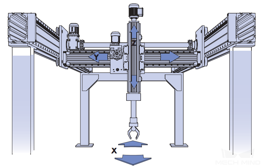
Degrees of Freedom of Gantry Robot
The gantry robot supports multi-degree-of-freedom movement, and the space angle between each degree of freedom is a right angle.
Gantry robots usually support 2 to 6 degrees of freedom, for example:
-
XYZ axes can move linearly (three degrees of freedom)
-
XYZ axes can move linearly, and the Z axis (called Rz or C axis) can rotate (four degrees of freedom)
-
XZ axes can move linearly (two degrees of freedom)
-
XZ axes can move linearly, and the Z axis can rotate (three degrees of freedom)
The camera is usually mounted on a certain axis of the gantry (such as the Z or C axis), and the camera’s scanning position will be affected by the movement of the axis. Therefore, in the pre-calibration configuration, you need to specify which axis movements will affect the camera’s position.
Left- and Right-handed Coordinate Systems
Mech-Mind Vision System uses the flange pose of the robot in the right-handed coordinate system to calculate the extrinsic parameters. Therefore, when using a gantry robot, you need to determine whether the gantry coordinate system is a right-handed coordinate system.
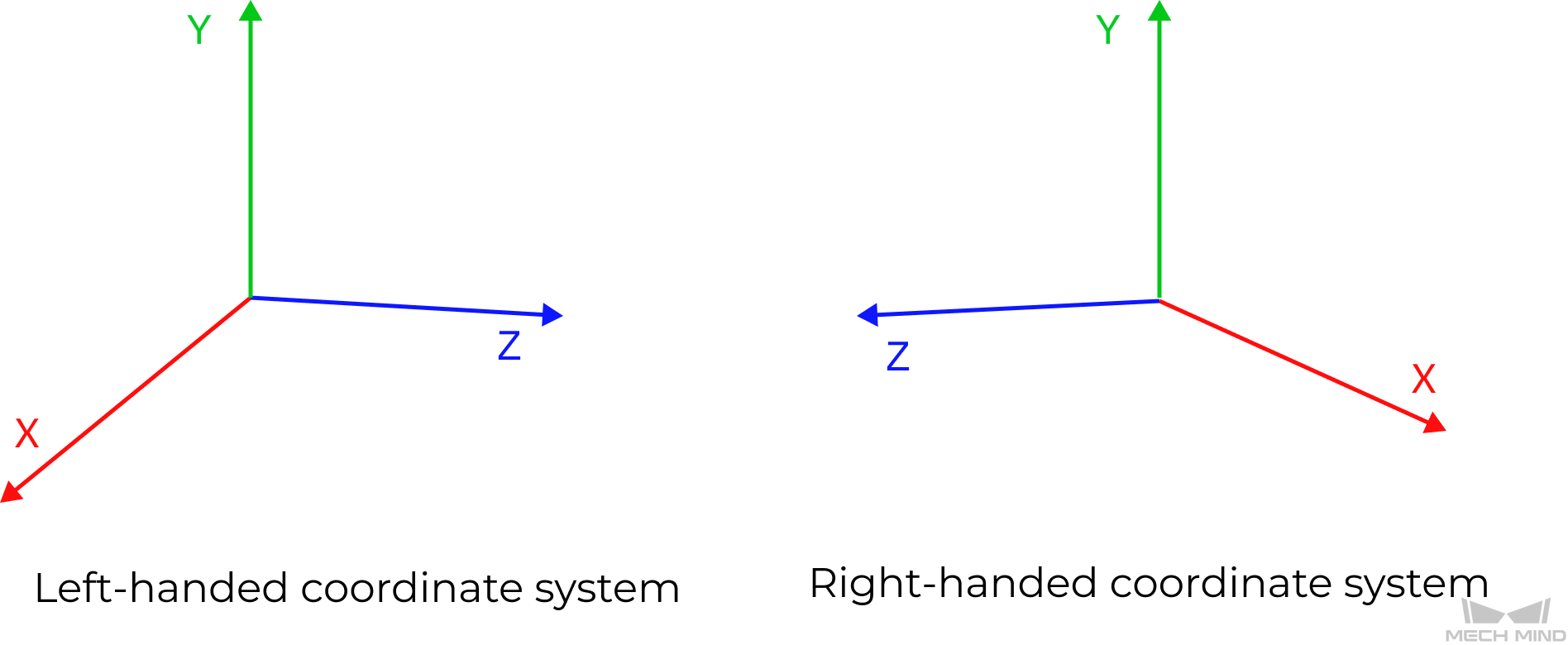
The left-handed and right-handed coordinate systems can be determined as follows:
-
Let the left thumb point to the positive direction of the X-axis, and the index finger point to the positive direction of the Y-axis. If the middle finger can point to the positive direction of the Z-axis, this coordinate system is called a left-handed coordinate system (see the left figure below).
-
Let the thumb of the right hand point to the positive direction of the X-axis, and the index finger point to the positive direction of the Y-axis. If the middle finger can point to the positive direction of the Z-axis, this coordinate system is called the right-hand coordinate system (see the right picture below).
When the gantry robot is a left-handed coordinate system, it is recommended to change it to a right-handed coordinate system to facilitate subsequent calibration and vision processing. Typically, you need to invert the positive direction of the encoder motion for either XYZ axis on a gantry robot. Generally, you just need to invert the axis installed on the gantry base, and then select the right-handed coordinate system in Mech-Vision for calibration.
If you can make this change on the gantry robot, you only need to select the left-handed coordinate system in Mech-Vision, and the software will automatically convert the input and output pose data.
Calibration Principles
For a gantry robot, the camera is usually mounted on a certain axis of the robot, such as the Z axis, that is, the camera is mounted in eye in hand (EIH) mode. The calibration of the gantry robot aims to determine the relative relationship between the camera reference frame and the robot tool reference frame.
Considering the limited freedom and activity space of the gantry robot, the Mech-Vision software uses the TCP touch method to collect calibration data and establish the relationship between the calibration board, camera and robot. In addition, the calibration process of the gantry robot supports adding the poses of multiple calibration boards. If the gantry robot cannot touch three points on the calibration board due to the limited degrees of freedom, you can use multiple calibration boards and control the gantry robot to touch three points (not in a line) on multiple calibration boards.
For the principles of the hand-eye calibration for gantry robots, please refer to the section Hand-Eye Calibration in the EIH Setup (TCP Touch).
Using the Extrinsic Parameter File
An extrinsic parameter file for the calibration point will be generated during the calibration of the gantry robot, and Mech-Vision will calculate the dynamic extrinsic parameters in real time according to the pose of the gantry robot. When calculating dynamic extrinsic parameters, the Mech-Vision project requires the use of the Transform Point Clouds for Truss and Transform Poses for Truss Steps to convert the point cloud/pose in the camera reference frame to the gantry reference frame.
When the project is running, please ensure that the gantry robot can communicate normally with the Mech-Mind Vision System. In addition, the robot program should provide the robot flange pose when triggering the Mech-Vision project to run, so that the "Capture Images from Camera" Step can successfully obtain the pose of the robot flange when capturing images.
|
If the gantry robot uses the left-handed coordinate system, the communication component automatically converts the robot flange poses sent by the robot program to those in the right-handed coordinate system, and then sends them to Mech-Vision for vision processing. When the vision result is returned, the communication component first automatically converts the poses in the gantry robot reference frame output by Mech-Vision to the poses in the left-handed coordinate system, and then returns them to the robot program. |