Auto-Switch Tool
Project Introduction
The example demonstrates how to auto-switch tools in the scenario of picking small sheet metal parts that are randomly stacked. The vision system guides the robot to switch to the appropriate tool based on different pick points, enabling smart picking from deep bins and ensuring a high bin clearance rate.
The application is as follows:
Application Scenario
-
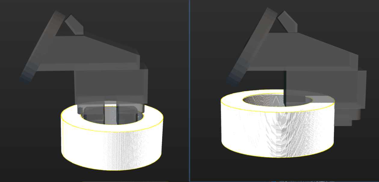
Suitable for the scenario of using the same tool to pick target objects in multiple ways. For example, to pick a ring, you can expand the claw gripper from the inside or close it from the outside.
-
Not suitable for the scenario where the robot needs to move to the tool-switching platform to switch tools.
| The example demonstrates the effect of using the same tool to pick target objects in multiple ways. |
Prerequisites
-
In the Master-Control communication mode, configure the control logic for the regular tool in the project resource tree.
-
In the project resource tree, click
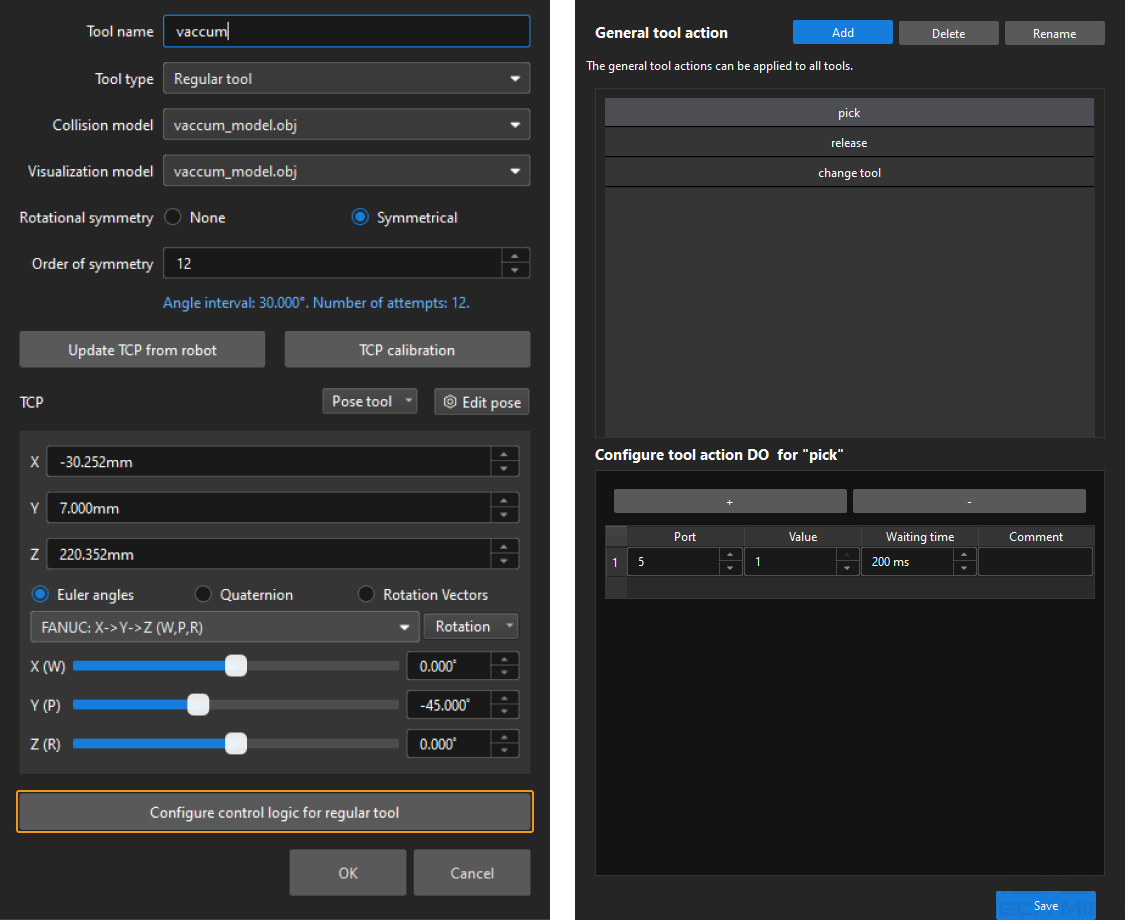
 on the right side of Tools to open the Tool Configuration window. Then, add the tool, and complete the relevant settings.
 -
Click the Configure control logic for regular tool at the bottom of the window and complete relevant configurations.
-
Add the action names shared by all tools in General tool action.
-
Configure DOs for the tool actions corresponding to different tools.
-
-
-
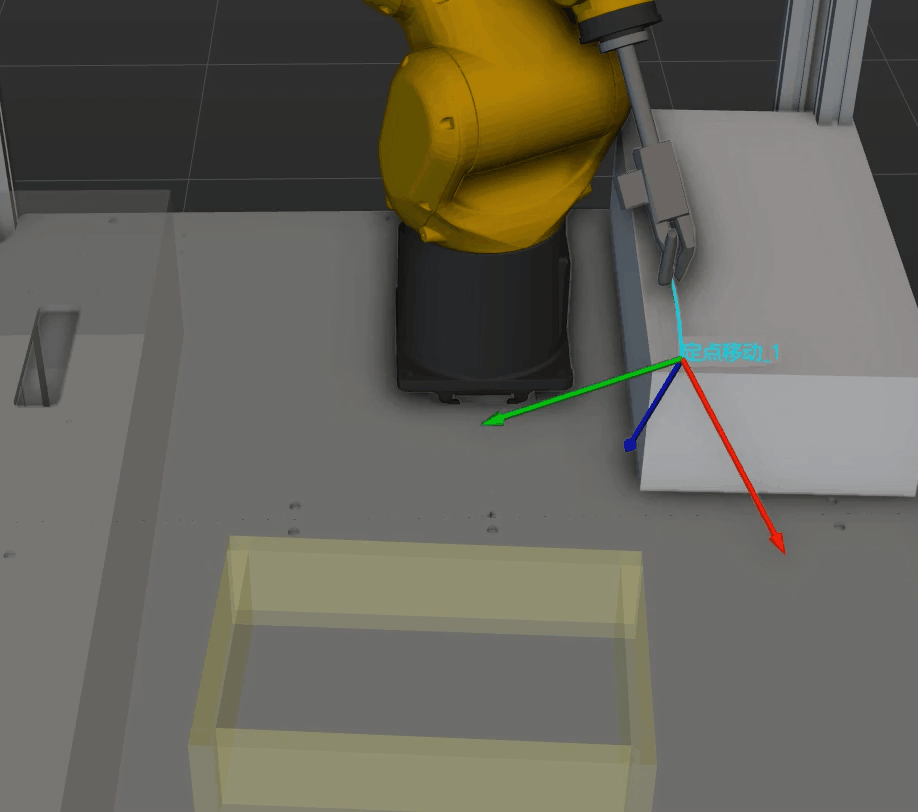
Configure the correspondence between pick points and tools in the target object editor.
When setting the pick point, you can enable the required tools from Tool list to facilitate previewing the relative positions of the tools and pick points in the target object editor. 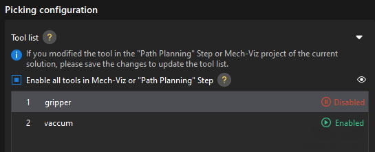
-
If using a standard interface program or Adapter for communication, you need to write a program for the robot end. This example project comes with example programs. You can download them from the software installation directory at
Communication Component/Robot_Interface/FANUC/sample/MM_S7_Viz_SwitchTCP. For more information about example programs, refer to Example Programs.
Workflow Description
-
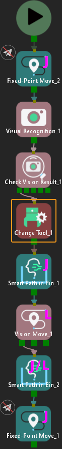
In the Standard Interface or Adapter communication mode, the position of the Change Tool Step in the workflow is shown below.
-
In the Master-Control communication mode, the workflow is shown below. Compared to the workflow in the Standard Interface and Adapter communication modes, Execute Tool Action is added to perform the corresponding tool actions.
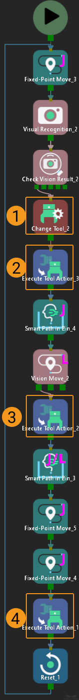
Key steps and their features in the workflow are listed in the table below.
No. Step Feature 1
Auto-switch to the appropriate tool
2
Adjust the corresponding tool to the initial pick state
3
Use the corresponding tool to execute the pick command
4
Use the corresponding tool to execute the place command
Parameter Description
-
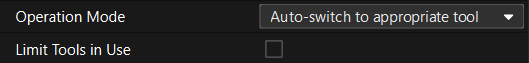
The Change Tool Step
In the step parameter area, set Operation Mode to Auto-switch to appropriate tool, and select Limit Tools in Use as needed. If not selected, the software will attempt to switch to the appropriate tool by trying all enabled tools in the target object editor.
-
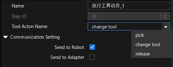
The Execute Tool Action Step
This Step can only be used in the Master-Control communication mode. Select the appropriate tool action for the phase from the drop-down menu of the Tool Action Name. Select Send to Robot in the Master-Control communication mode.
Notes
To apply this example in actual production, you can modify and configure the project based on the following notes to quickly put it into use.
-
Close vision records, and call the corresponding Mech-Vision project to obtain vision results by the Vision Recognition Step.
-
Configure Scene objects and Tools models.
-
Configure the parameters in the collision detection functional panel.
-
If the Standard Interface communication is used, you can refer to Example Programs to write a program for the robot end.