Status Codes and Troubleshooting
Overview
Status codes in the Standard Interface commands returned by the vision system in are 4-digit numbers that represent the status of command execution. Status codes are divided into normal status codes and error codes. Normal status codes indicate that the command is executed successfully, while error codes indicate that an error occurs during command execution. You may address errors by referring the error code descriptions in this guide. The following table classifies status codes into different categories.
| Status code | Description |
|---|---|
1001-1099 |
|
1100-1199 |
|
2001-2099 |
|
2100-2199 |
|
3001-3099 |
|
3100-3199 |
|
4001-4099 |
|
4100-4199 |
Robot normal status codes |
7001-7099 |
|
6001~6199 |
Status codes that can be customized in Mech-Vision |
7100-7199 |
Mech-Vision
Mech-Vision error codes
| Error code | Description |
|---|---|
Mech-Vision: Unregistered project existed in the solution |
|
Mech-Vision: No vision result |
|
Mech-Vision: No point cloud in ROI |
|
Mech-Vision: Invalid command parameter to start Mech-Vision project |
|
Mech-Vision: Invalid pose data |
|
Mech-Vision: Project is running |
|
Mech-Vision: Digital output signal list not provided |
|
Mech-Vision: Number of poses and number of labels do not match |
|
Mech-Vision: Project ID does not exist |
|
Mech-Vision: Parameter recipe ID does not exist |
|
Mech-Vision: Parameter recipe not configured |
|
Mech-Vision: Failed to switch parameter recipe |
|
Mech-Vision: Project execution error |
|
Mech-Vision: Data obtained by the command does not match the Port Type value of the Output Step. Please select a proper command or modify the Port Type value |
|
Mech-Vision: Failed to map the string of label to numbers |
|
Mech-Vision: Invalid pose number input |
|
Mech-Vision: Execution timeout |
|
Mech-Vision: Project not started |
|
Mech-Vision: Failed to set object dimensions |
|
Mech-Vision: Invalid object dimension settings |
|
Mech-Vision: Failed to connect to camera |
|
Mech-Vision: Number of poses and list size of custom port data do not match |
|
Mech-Vision: Visual image data in use. The running cannot proceed |
|
Mech-Vision: Invalid pose type |
|
Mech-Vision: Runtime error at Path Planning Step |
|
Mech-Vision: Robot cannot reach the waypoint |
|
Mech-Vision: Motion singularity error |
|
Mech-Vision: Invalid pick point |
|
Mech-Vision: Robot collision detected |
|
Mech-Vision: No available placing position for palletizing |
|
Mech-Vision: No vision point for the Vision Move Step |
|
Mech-Vision: Invalid tool |
|
Mech-Vision: Timeout occurs when waiting for the capture completion |
|
Mech-Vision: Box mask recognition error |
|
Mech-Vision: Check box dimensions error |
|
Mech-Vision: Failed to set pose |
Mech-Vision normal status codes
| Normal status code | Description |
|---|---|
1100 |
Mech-Vision: Get vision result successfully |
1101 |
Mech-Vision: Ready to run |
1102 |
Mech-Vision: Project get triggered successfully |
1103 |
Mech-Vision: Obtained planned path successfully |
1106 |
Mech-Vision: Obtain DO signal list successfully |
1107 |
Mech-Vision: Parameter recipe switched successfully |
1108 |
Mech-Vision: Object dimensions input to the project successfully |
1110 |
Mech-Vision: Pose set successfully |
Mech-Viz
Mech-Viz error codes
| Error code | Description |
|---|---|
Mech-Viz: Software not registered |
|
Mech-Viz: Project is running |
|
Mech-Viz: Robot cannot reach the waypoint |
|
Mech-Viz: Invalid command parameter to start Mech-Viz |
|
Mech-Viz: Runtime error |
|
Mech-Viz: Digital output signal list not provided |
|
Mech-Viz: Invalid pose type |
|
Mech-Viz: Invalid pose data |
|
Mech-Viz: No project set to autoload |
|
Mech-Viz: Failed to set Step parameter value |
|
Mech-Viz: Failed to stop execution |
|
Mech-Viz: Invalid branch exit port number |
|
Mech-Viz: Failed to set branch |
|
Mech-Viz: Motion singularity error |
|
Mech-Viz: The project has not been executed or has no results after execution |
|
Mech-Viz: Invalid Branch Step ID |
|
Mech-Viz: Execution timeout |
|
Mech-Viz: Invalid Step ID of index-type Steps |
|
Mech-Viz: Invalid Current Index value |
|
Mech-Viz: Failed to set index |
|
Mech-Viz: Invalid pick point |
|
Mech-Viz: Robot collision detected |
|
Mech-Viz: No available placing position for palletizing |
|
Mech-Viz: Visual Recognition Step not called |
|
Mech-Viz: No vision result received from vision service |
|
Mech-Viz: No point cloud in ROI |
|
Mech-Viz: No vision point for the Vision Move Step |
|
Mech-Viz: Failed to get Step parameter |
|
Mech-Viz: Failed to get planning result in Vision Move |
|
Mech-Viz: Failed to get custom data |
|
Mech-Viz: Vision service not registered |
|
Mech-Viz: Invalid tool |
|
Mech-Viz: Check box dimensions error |
Mech-Viz normal status codes
| Normal status code | Description |
|---|---|
2100 |
Mech-Viz: Execution completed successfully |
2102 |
Mech-Viz: DO signal list obtained successfully |
2103 |
Mech-Viz: Started successfully |
2104 |
Mech-Viz: Stopped successfully |
2105 |
Mech-Viz: Set branch successfully |
2106 |
Mech-Viz: Set index successfully |
2107 |
Mech-Viz: Set move point for External Move Step successfully |
2108 |
Mech-Viz: Set Step parameter value successfully |
2109 |
Mech-Viz: Get Step parameter value successfully |
Communication Component
Communication Component error codes
| Error code | Description |
|---|---|
Communication Component: Invalid command |
|
Communication Component: Invalid data length or format for command parameter |
|
Communication Component: Mech-Vision timed out |
|
Communication Component: Unknown error |
|
Communication Component: Data acknowledge signal timed out |
|
Communication Component: Configuration ID does not exist |
Calibration
Mech-Vision Troubleshooting
1001
Mech-Vision: Unregistered project existed in the solution
Cause:
-
Mech-Vision was not started.
Solution:
-
Ensure that the Mech-Vision software is started.
1002
Mech-Vision: No vision result
Cause:
-
The Mech-Vision project was successfully executed, but the ports of the Output Step failed to output data. Possible reasons include exceedingly high confidence threshold for instance segmentation, no matched object in the scene, improper ROI settings, low point cloud quality, improper filtering settings, etc.
Solution:
-
Enable Debug Output: Open Mech-Vision, turn on the Debug Output switch, click Run or Single Step Execution, double-click to connect Steps, and then view the detailed output in the right Debug Output window.
-
Locate the problematic Step: Start from the first Step and sequentially check the data flow of each port of the Step from top to bottom. If the data flow of a Step is abnormal, the Step is problematic.
-
Check the parameters of the problematic Step: Make sure that all necessary Steps are properly configured, and the data can flow naturally.
The parameters of the following Steps are essential for the output. If the project contains the following Steps, pay attention to the Step parameter values.
-
Extract 3D Points in 3D ROI: In the 3D ROI Settings section, click Open the editor and make sure that the point cloud of the target object locates within the green box.
-
3D Matching: Adjust the Confidence Threshold value based on the matching result in the visualized output and actual situation.
-
If Confidence Threshold is set to a high value, such as 0.9 or higher, the detection object will only be marked as a valid match when the model is highly accurate in its detection results. In this case, it is advisable to lower the confidence threshold to a more appropriate level, such as 0.5 or 0.6, to balance the risk of missing detections.
-
If adjusting the confidence threshold does not yield satisfactory results, it is necessary to use a more diverse and challenging dataset in model training to make the instance segmentation applicable to more scenarios.
-
-
1003
Mech-Vision: No point cloud in ROI
Cause:
-
There was no point cloud in the 3D ROI.
| This error can be a signal that the bin is empty or out of position. Thus it’s not necessarily a project execution error that needs to be fixed. |
Solution:
-
Check the ROI setting in the project and ensure the setting is proper.
1005
Mech-Vision: Invalid command parameter to start Mech-Vision project
Cause:
-
In the command sent by the robot side to trigger the Mech-Vision project, the value of the robot pose type parameter was invalid. The value range of the robot pose type parameter is 0 to 3.
-
In the command sent by the robot side to trigger the Mech-Vision project and obtain results, the value of the returned data format parameter was invalid. The value range of returned data format is 1 to 4.
Solution:
-
Ensure the parameter values in the command sent by the robot side are within the valid range.
1006
Mech-Vision: Invalid pose data
Cause:
-
In the command sent by the robot side to trigger the Mech-Vision project, the value of the robot pose parameter was invalid. Possible scenarios are as follows:
-
The value of the joint positions were less than 6 fields.
-
The value of the flange pose were less than 6 fields.
-
The value of the flange pose was all 0.
-
| By default, a 6-axis robot is used and thus the value of the “robot pose” parameter occupies six fields. If a 4-axis or 5-axis robot is used, fill in the empty fields with 0. |
Solution:
-
Ensure that the robot pose parameter is set correctly, which means to ensure that the joint positions or flange pose is set correctly.
1007
Mech-Vision: Project is running
Cause:
-
While the Mech-Vision project was running, the robot side sent the command to start it again.
| Mech-Vision allows concurrent running of multiple projects, but one Mech-Vision project cannot be started again when it is already running. |
Solution:
-
Ensure that the Mech-Vision project ID set in the robot program is correct.
-
Ensure that the robot program does not contain code that triggers the same Mech-Vision project in a short period of time. When running the same project, the client must wait for the project to finish before running it again to avoid encountering this error. If the project finishes running, a message that indicates the project execution has been stopped will be displayed in the Vision tab of the Log panel in Mech-Vision.
1008
Mech-Vision: Digital output signal list not provided
Cause:
-
The DO signal list for the vacuum gripper obtained from Mech-Vision was empty.
Solution:
-
Ensure that the tool type in the path planning tool is depalletizing vacuum gripper and DO signals are configured correctly in the vacuum gripper configuration interface.
1010
Mech-Vision: Number of poses and number of labels do not match
Cause:
-
In the Output Step of the Mech-Vision project, the number of poses output by the poses port was not equal to the number of labels output by the labels port.
Solution:
-
Check the data flow of the Mech-Vision project to ensure the number of poses and the number of labels are the same. For example, in the following figure, the Size parameter of the poses port and that of the labels port are both set to 2, which means that the number of poses and the number of labels are the same. If the Size parameter of the poses port is set to 3 and that of the labels port is set to 2, the number of poses and the number of labels are not the same. The preceding occur will occur.
1011
Mech-Vision: Project ID does not exist
Cause:
-
The project ID specified in the command sent by the robot side did not exist in the project list of Mech-Vision. For example, when there is only a project with an ID of 1 in the project list, and the project ID specified in the command is 2, this error will prompt.
Solution:
-
Ensure that Autoload Project is selected.
-
Ensure that the project ID specified in the command sent by the robot side exists in the project list of Mech-Vision.
1012
Mech-Vision: Parameter recipe ID does not exist
Cause:
-
The parameter recipe ID specified in the command sent by the robot side did not exist in the Parameter Recipe Editor. For example, when there is only a parameter recipe with an ID of 1 in the Parameter Recipe Editor, and the parameter recipe ID specified in the command is 2, this error will occur.
Solution:
-
Ensure that the parameter recipe ID specified in the command sent by the robot side exists in the Parameter Recipe Editor.
1013
Mech-Vision: Parameter recipe not configured
Cause:
-
The robot side sent the command to switch the parameter recipe of Mech-Vision, but the Mech-Vision project did not have any parameter recipe.
Solution:
-
Check the parameter recipe setting in the Mech-Vision project and ensure that the parameter recipe and its ID are correct.
-
The robot does not necessarily need to send the parameter switching command if not needed by Mech-Vision.
1014
Mech-Vision: Failed to switch parameter recipe
Cause:
-
Mech-Vision had exhibited abnormal behavior in Standard Interface communication, which resulted in the failure of parameter recipe switch.
Solution:
-
Contact Mech-Mind Technical Support.
1015
Mech-Vision: Project execution error
Cause:
-
A runtime error occurred in the Mech-Vision project.
| This status code only indicates that an error has occurred when the Mech-Vision project was operating. Specific reasons for the error was not provided. |
Solution:
-
Check the error message in the log panel of Mech-Vision and modify the project if necessary.
1016
Mech-Vision: Data obtained by the command does not match the Port Type value of the Output Step. Please select a proper command or modify the Port Type value
Cause:
-
When the client calls the Get Vision Result command, the Port Type parameter of the Output Step in the Mech-Vision project is not set to Predefined (vision result).
-
When the client calls the Get Mech-Vision Custom Data command, the Port Type parameter of the Output Step in the Mech-Vision project is not set to Custom.
-
When the client calls the Get Mech-Vision Planned Path command, the Port Type parameter of the Output Step in the Mech-Vision project is not set to Predefined (robot path).
Solution:
-
Check the value of the Port Type parameter of the Output Step in the Mech-Vision project.
-
If the client calls the Get Vision Result command, the Port Type parameter of the Output Step in the Mech-Vision project must be set to Predefined (vision result).
-
If the client calls the Get Mech-Vision Custom Data command, the Port Type parameter of the Output Step in the Mech-Vision project must be set to Custom.
-
If the client calls the Get Mech-Vision Planned Path command, the Port Type parameter of the Output Step in the Mech-Vision project must be set to Predefined (robot path).
-
1017
Mech-Vision: Failed to map the string of label to numbers
Cause:
-
The data output by the labels port of the Output Step in Mech-Vision was not an integer-formatted string.
Solution:
-
Check the data output by the labels port of the Output Step. If the data is not an integer-formatted string, add a Label Mapping Step before the Output Step to transform the output of the labels port to an integer-formatted string. For example, in the figure below, the Label Mapping Step maps the string label OK to the integer-formatted string 0 and the string label NG to the integer-formatted string 1.
1018
Mech-Vision: Invalid pose number input
Cause:
-
In the command sent by the robot side to trigger the Mech-Vision project, the value of the expected number of vision points or waypoints parameter exceeded the maximum number of poses that could be sent each time.
| From the toolbar of Mech-Vision, go to . Modify the value of max num of poses to send per time. The limit is 30. |
Solution:
-
Ensure that the expected number of vision points or waypoints parameter value is no greater than maximum number of poses that could be sent each time.
1019
Mech-Vision: Execution timeout
Cause:
-
Since the robot side sent the command to get vision results, the Mech-Vision project had not finished execution within the timeout period. The default timeout period is 10s.
| From the toolbar of Mech-Vision, go to . Modify the value of Timeout for getting Mech-Vision data(s) to change the timeout setting. |
Solution:
-
You can add a delay command in the robot program before the command that obtains the vision results.
-
For Mech-Vision projects that takes a relatively long time to finish running, users may modify the timeout period according to needs.
1020
Mech-Vision: Project not started
Cause:
-
The robot side sent the command to obtain vision results before sending the command to trigger the Mech-Vision project. For example, there are two projects with IDs 1 and 2 on the project list of Mech-Vision. If the robot side triggers project 1 but requires obtaining vision results from object 2, this error will occur.
-
The robot side had obtained all vision results but was still sending the command to obtain more vision results.
Solution:
-
Check the robot program and ensure that the Mech-Vision project ID in the command sent by the robot side to obtain vision results is correct.
-
When the status of transmitting vision points parameter in the returned data is set to 1, it indicates that all vision points have been obtained. In this case, robot should stop sending the command that obtains vision results.
1021
Mech-Vision: Failed to set object dimensions
Cause:
-
The Mech-Vision project did not contain a Read Object Dimensions Step.
Solution:
-
Ensure that there is a Read Object Dimensions Step in the Mech-Vision project.
1022
Mech-Vision: Invalid object dimension settings
Cause:
-
The object dimensions sent to the Mech-Vision project had 0 or a negative value.
Solution:
-
Ensure that the object dimensions (length, width, height) are all positive integers.
1023
Mech-Vision: Failed to connect to camera
Cause:
-
The Capture Images from Camera Step in the Mech-Vision project failed to connect to a camera.
Solution:
-
Check the camera power supply and network settings to ensure that both the camera power and network are properly connected.
-
Ensure that the IP address and port set in the Capture Images from Camera Step are correct.
1024
Mech-Vision: Number of poses and list size of custom port data do not match
Cause:
-
The list length of the poses port and list length of the custom port of the Output Step of the Mech-Vision project did not match. For example, consider the pose list as [[1,1,1,0,1,0,0]],[1,1,1,0,0,0,0]]. If the data list output by the custom port is [[1,1]] or [], the lengths of the two lists are not equal; while if the data list output by the custom port is [1,1], the lengths of the two lists are the same.
Solution:
-
Check the poses and the custom port data in the data flow of the Mech-Vision project to ensure the lengths of the two lists match. For example, in the following figure, the Size parameter of the poses port and that of the custom port are both set to 2, which means that the lengths of the two lists match. If the Size parameter of the poses port is set to 3 and that of the custom port is set to 2, the lengths of the two lists do not match. The preceding occur will occur.
1025
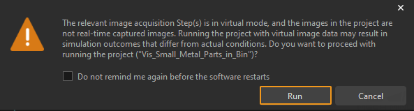
Mech-Vision: Visual image data in use. The running cannot proceed
Cause:
-
The image used by the Capture Images from Camera Step in the Mech-Vision project is a virtual image from your computer and not an image captured by the actual camera.
Solution:
-
In the Camera Settings section of the Capture Images from Camera Step, check to make sure that Virtual Mode is disabled.
-
If the virtual mode is needed, click Run in the following dialog box. This way, the data will be sent. In addition, we recommend that you select Do not remind me again before the software restarts.
1026
Mech-Vision: Invalid pose type
Cause:
-
In the command sent by the robot side to obtain planned path from Mech-Vision, the value of the waypoint pose type parameter was invalid. The value of the waypoint pose type parameter can only be 1 or 2.
Solution:
-
Ensure the parameter values in the command sent by the robot side are within the valid range.
1027
Mech-Vision: Runtime error at Path Planning Step
Cause:
-
An error occurred when the Mech-Vision project was executing the Path Planning Step.
| This status code only indicates that an error has occurred in the Path Planning Step. Specific reasons for the error are not yet provided. |
Solution:
-
Open the path planning tool and check the log to identify the root cause.
1030
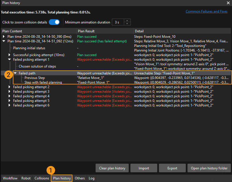
Mech-Vision: Robot cannot reach the waypoint
The Path Planning Step prompted the error. Possible causes are as follows:
-
The waypoint was out of reach for the robot.
-
Robot inverse kinematic solution failed.
Solution:
-
Open the configuration wizard of the Path Planning Step, view the plan history to locate the red content, and then locate the specific Step where the issue occurred.
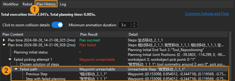
-
To troubleshoot Waypoint unreachable, perform the following operations:
-
Check the waypoint pose: Ensure that the pose is correctly oriented and reachable. Note the difference between the object’s pose and the TCP.
-
Check the TCP: Make sure that the TCP in the Path Planning Step is the same as the actual TCP of the robot.
-
1033
Mech-Vision: Motion singularity error
The Path Planning Step prompted the error. Possible causes are as follows:
-
The robot detected an singularity error during path planning. The joint velocity or joint acceleration of the real robot exceeded the threshold values of detecting singularity set in the software.
-
The robot could not reach the point by moving in the planned straight line.
Solution:
-
If the singularity detection threshold is too strict, users may consider reducing the values of Max velocity or Reduction ratio. To change the threshold of singularity detection, contact Mech-Mind Technical Support.
-
If the robot cannot reach the point by moving in a straight line, users may consider changing the motion type to joint motion or adding intermediate waypoints.
1035
Mech-Vision: Invalid pick point
Cause:
-
None of the pick points are within the bin.
-
The tool set for the pick point in the workobject library does not match the tool selected in the path planning tool.
Solution:
-
For the first cause:
-
Make sure that extrinsic parameters of the camera are properly set.
-
In the Output Step of the Mech-Vision project, make sure that the pose of the workobject pick point is the same as the actual workobject pose.
-
In the Path Planning Step of the Mech-Vision project, click Config Wizard to go to the path planning tool and make sure that the specified location of the bin is the same as the actual location of the bin.
-
-
For the second cause:
-
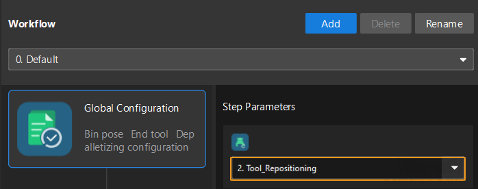
In the workobject library, check to make sure that a valid tool is configured for a pick point. For example, the valid tool for PickPoint_2 is Tool_Repositioning in the following figure.
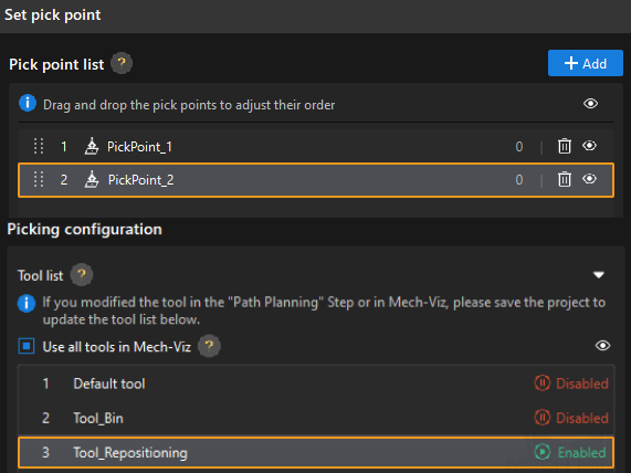
-
In Global Configuration of the path planning tool, check to make sure that the selected tool is a valid tool in the tool list for the pick point.
-
1036
Mech-Vision: Robot collision detected
The Path Planning Step prompted the error. Possible causes are as follows:
-
The robot was at risk of colliding with scene objects.
-
The robot was at risk of colliding with the point cloud of the object.
Solution:
-
If the robot is at risk of colliding with scene objects, users may consider adding intermediate waypoints for the robot to avoid these objects.
-
If the robot is at risk of colliding with the point cloud of the object, users may consider adjusting the threshold of detecting collision with the point cloud.
-
If an error occurs in the home position of the planned path, users may consider setting the HOME position.
1037
Mech-Vision: No available placing position for palletizing
Cause:
-
The tray is full. No position is available for palletizing.
Solution:
-
Add the appropriate handling logic at the failed planning exit port of palletizing-type steps.
1044
Mech-Vision: No vision point for the Vision Move Step
The Path Planning Step prompted the error. Possible causes are as follows:
-
The input port of the Path Planning Step did not receive pose data of vision points.
Solution:
-
Check the Vision Points port of the Path Planning Step, and ensure that the port has received poses.
1046
Mech-Vision: Invalid tool
The Path Planning Step prompted the error. Possible causes are as follows:
-
The tool was invalid.
Solution:
-
In the path planning tool interface, check and ensure that the tool settings and the Global Configuration settings are correct.
1047
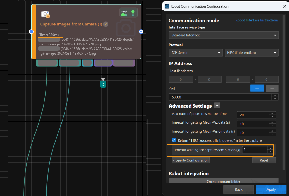
Mech-Vision: Timeout occurs when waiting for the capture completion
Cause:
-
The Capture Images from Camera Step did not complete execution within the timeout period set by Timeout waiting for capture completion(s).
Solution:
-
Select Robot Communication Configuration on the toolbar. Click Next and then click Advanced Settings. Check Timeout waiting for capture completion(s) (only available when Return ‘1102: visible after the Successfully triggered checkbox).
-
Compare the value of “Timeout waiting for capture completion(s)” and the execution time of the “Capture Images from Camera” Step. If the value of “Timeout waiting for capture completion(s)” is smaller than the execution time of the “Capture Images from Camera” Step, adjust the value of “Timeout waiting for capture completion(s)” to make it greater than the execution time of the “Capture Images from Camera” Step. For example, in the figure below, the value of “Timeout waiting for capture completion(s)” is greater than the execution time of the “Capture Images from Camera” Step, which means that this setting in the figure below is valid.
1048
Mech-Vision: Box mask recognition error
Cause:
-
The Mech-Vision project validated the masks of the box objects with the Validate Box Object Masks Step. However, the validation failed because the box objects did not meet the criteria set in the Step Parameters panel, including of All Boxes Must Be Same Dimension, All Boxes Must Be Detected and Rectangularity Validation.
Solution:
-
Check the Validate Box Object Masks Step and ensure that the input data and parameter values are correct.
1049
Mech-Vision: Check box dimensions error
Cause:
-
The Mech-Vision project validated the masks of the box objects with the Validate Box Dimensions Step. However, the validation failed because the dimensions calculated from the masks did not match the data set in the Box Dimension Information in the Step Parameters panel.
Solution:
-
Check the Validate Box Dimensions Step and ensure that the input data and parameter values are correct.
1051
Mech-Vision: Failed to set pose
Cause:
-
When the client calls the command to input poses to the Mech-Vision project, the Step name is not a number or the Step corresponding to the Step name is not Easy Create Poses.
Solution:
-
Check the Easy Create Poses Step in the Mech-Vision project to make sure that the Step name is a number.
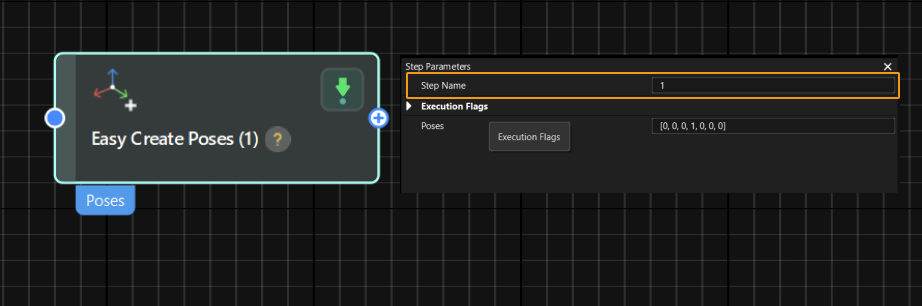
-
Check the command to input poses to the Mech-Vision project to make sure that the Step name set in the command matches the Step name in the above figure.
Mech-Viz Troubleshooting
2001
Mech-Viz: Software not registered
Cause:
-
Mech-Viz was not started.
-
Multiple Mech-Viz windows were opened under the developer mode.
Solution:
-
Ensure that the Mech-Viz software is started.
-
Exit the developer mode and restart Mech-Viz.
2002
Mech-Viz: Project is running
Cause:
-
While the Mech-Viz project was running, the robot side sent the command to start it again.
Solution:
-
Ensure that the robot program does not contain codes that trigger the same Mech-Viz project in a short period of time.
2004
Mech-Viz: Robot cannot reach the waypoint
Cause:
-
The waypoint was out of reach for the robot.
-
If the Mech-Viz project contains a Change Tool Step and the TCP changes before and after switching tools, the robot may fail to reach the waypoint.
Solution:
-
Open the Mech-Viz software, view the plan history to locate the red content, and then locate the specific Step where the issue occurred.
-
To troubleshoot Waypoint unreachable, perform the following operations:
-
Check the waypoint pose: Ensure that the pose is correctly oriented and reachable. Note the difference between the object’s pose and the TCP.
-
Check the TCP: Make sure that the TCP in Mech-Viz is the same as the actual TCP of the robot.
-
Check soft limits: Check if the soft limits are properly set. To check the soft limits, select in the lower-right corner of Mech-Viz.
-
2006
Mech-Viz: Invalid command parameter to start Mech-Viz
Cause:
-
In the command sent by the robot side to trigger the Mech-Viz project, the value of the robot pose type parameter was invalid. The value range of robot pose type is 0 to 2.
Solution:
-
Ensure the parameter values in the command sent by the robot side are within the valid range.
2008
Mech-Viz: Runtime error
Cause:
-
An error occurred when the Mech-Viz project was running.
Solution:
-
Open Mech-Viz and check the log to identify the root cause.
2011
Mech-Viz: Digital output signal list not provided
Cause:
-
The DO signal list for the vacuum gripper obtained from Mech-Viz was empty.
Solution:
-
Ensure that there is a Set DO Step following the Vision Move Step, and that Receiver is set to Standard Interface on the Step parameters panel of the Set DO Step.
-
Ensure that the tool type is set to depalletizing vacuum gripper and DO signals are configured correctly in the vacuum gripper configuration interface.
2012
Mech-Viz: Invalid pose type
Cause:
-
In the command sent by the robot side to obtain planned path from Mech-Viz, the value of the waypoint pose type parameter was invalid. The value of the waypoint pose type parameter can only be 1 or 2.
-
When you call the "run Mech-Viz project and obtain planned path" command, the value of the waypoint pose type parameter was invalid. The value of the waypoint pose type parameter can only be 1 or 2.
Solution:
-
Ensure the parameter values in the command sent by the robot side are within the valid range.
2013
Mech-Viz: Invalid pose data
Cause:
-
In the command sent by the robot side to trigger the Mech-Viz project, the value of the robot pose parameter was invalid. Possible scenarios are as follows:
-
The value of the joint positions were less than 6 fields.
-
The value of the flange pose were less than 6 fields.
-
The value of the flange pose was all 0.
-
| By default, a 6-axis robot is used and thus the value of the robot pose parameter occupies six fields. If a 4-axis or 5-axis robot is used, fill in the empty fields with 0. |
Solution:
-
Ensure the robot pose parameter value is appropriate.
2014
Mech-Viz: No project set to autoload
Cause:
-
The Mech-Viz project was not running.
-
The Mech-Viz project was not set to autoload.
Solution:
-
Ensure the project used by the robot side is open in Mech-Viz and has the Autoload Project option checked.
2016
Mech-Viz: Failed to set Step parameter value
Cause:
-
An error occurred when the robot side sent the command to set Mech-Viz Step parameter value.
Solution:
-
Ensure that the Step ID and parameter key name in the property_config file are correct.
| From the toolbar of Mech-Vision, go to . Click Property Configuration to open the property_config file. |
2017
Mech-Viz: Failed to stop execution
Cause:
-
Since the robot side sent the command to stop the Mech-Viz project, the project had not stopped running in 5s.
Solution:
-
Contact Mech-Mind Technical Support.
2018
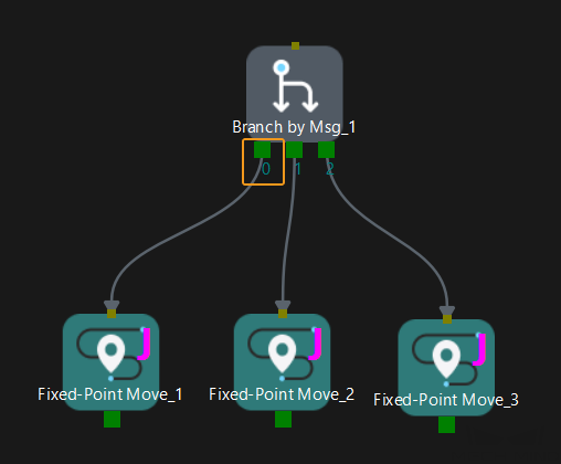
Mech-Viz: Invalid branch exit port number
Cause:
-
In the command sent by the robot side to set the exit port for the Branch by Msg Step in Mech-Viz, the exit port parameter value was equal to or smaller than 0, or the value was larger than the number of the ports of the Branch by Msg Step.
Solution:
-
Open the Mech-Viz project, find the Branch by Msg Step on the Workflow tab, and then make sure that the exit port number set in the command matches the exit port of the Branch by Msg Step. For example, if the exit port number is set to 1 in the command, the Mech-Viz project takes the exit port 0 of the Branch by Msg Step.
2019
Mech-Viz: Failed to set branch
Cause:
-
The Step ID parameter in the command sent by the robot side to set the exit port for the Branch by Msg Step in Mech-Viz did not have a corresponding Branch by Msg Step in the Mech-Viz project.
Solution:
-
Ensure that the Step ID in the command sent by the robot side has a corresponding Step in the Mech-Viz project.
2020
Mech-Viz: Motion singularity error
Cause:
-
The robot detected an singularity error during path planning. The joint velocity or joint acceleration of the real robot exceeded the threshold values of detecting singularity set in Mech-Viz.
-
The robot could not reach the point by moving in the planned straight line.
Solution:
-
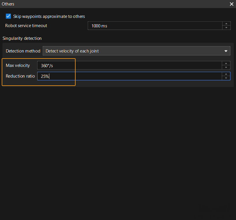
If the singularity detection threshold in Mech-Viz is too strict, modify the value of Max velocity or Reduction ratio on the Others tab in Mech-Viz.
-
Max velocity: The maximum allowable angular velocity for each joint of the robot.
-
Reduction ratio: When the detected velocity of any joint exceeds the specified Max velocity value, the velocity set in the move-type Step in Mech-Viz will be reduced according to the Reduction ratio value (new velocity = original velocity × reduction ratio), and the singularity detection will be performed again. If the reduced velocity is less than the set max velocity, the robot will move at the reduced velocity in the corresponding Step. If the reduced velocity still exceeds the set max velocity, the Mech-Viz software will determine that a singularity will occur due to the planned path. This means that the planned path cannot pass the singularity detection.
-
-
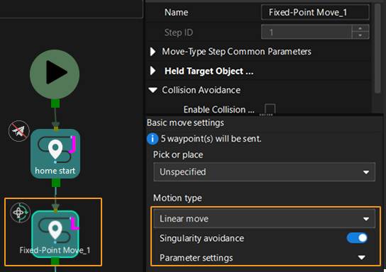
If the robot cannot move linearly, try Method 1 first. If the issue persists, try either one of the remaining methods.
-
Method 1: In Mech-Viz, select the move-type Step that causes the error, set Motion type to Linear move, enable Singularity avoidance, and then set parameters based on actual conditions.
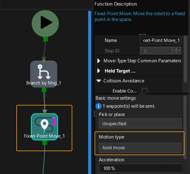
-
Method 2: In Mech-Viz, select the move-type Step that causes the error and set Motion type to Joint move.
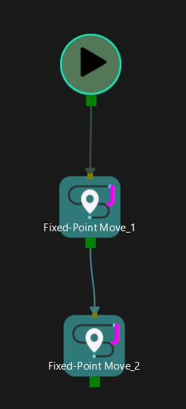
-
Method 3: In Mech-Viz, add one or more move-type Steps before the Step that causes the error. This means adding intermediate waypoints. For example, in the figure below, Fixed-Point Move_3 is added between Fixed-Point Move_1 and home. This means that an intermediate waypoint is added.
-
2022
Mech-Viz: The project has not been executed or has no results after execution
Cause:
-
When the robot side sent the command to set the exit port for the Branch by Msg Step in Mech-Viz, the Mech-Viz project was not running.
-
Before sending the command to obtain the planned path, the robot side did not send the command to trigger the Mech-Viz project.
-
When the robot side sent the command to obtain the planned path from Mech-Viz, Mech-Viz had not output the planned result.
-
The robot side had obtained all waypoints but was still sending the command to obtain the planned path from Mech-Viz.
Solution:
-
Ensure that the Mech-Viz project is running when the robot side sends the command to set the exit port for the Branch by Msg Step. After the command to run the Mech-Viz project is called, make sure that the Mech-Viz project is running, as shown in the figure below, and then call the command to set the exit port of the Branch by Msg Step in Mech-Viz.
-
Ensure that the robot side sends the command to trigger the Mech-Viz project BEFORE sending the command to obtain the planned path.
-
When the status of transmitting waypoints parameter in the returned data is set to 1, it indicates that all waypoints have been obtained. In this case, the robot side should stop sending the command to obtain the planned path from Mech-Viz.
2024
Mech-Viz: Invalid Branch Step ID
Cause:
-
In the command sent by the robot side to set the exit port for the Branch by Msg Step in Mech-Viz, the Step ID parameter value was not a positive integer.
Solution:
-
Ensure that the Step ID in the command sent by the robot side is a positive integer.
2025
Mech-Viz: Execution timeout
Cause:
-
Since the robot side sent the command to get the planned path, the Mech-Viz project had not finished execution within the timeout period. The default timeout period is 10s.
| From the toolbar of Mech-Vision, go to . Modify the value of Timeout for getting Mech-Viz data(s) to change the timeout setting. |
Solution:
-
You can add a delay command in the robot program before the command that obtains the planned path from Mech-Viz.
-
For Mech-Viz projects that takes a relatively long time to finish running, users may modify the timeout period according to needs.
2026
Mech-Viz: Invalid Step ID of index-type Steps
Cause:
-
In the command sent by the robot side to set the Current Index for Mech-Viz, the Step ID parameter value was not a positive integer.
Solution:
-
Ensure that the Step ID in the command sent by the robot side is a positive integer.
2027
Mech-Viz: Invalid Current Index value
Cause:
-
In the command sent by the robot side to set the Current Index for Mech-Viz, the Current Index parameter value was not a positive integer.
Solution:
-
Ensure that the Current Index parameter value in the command sent by the robot is a positive integer.
2028
Mech-Viz: Failed to set index
Cause:
-
The Step ID parameter in the command sent by the robot side to set the Current Index for Mech-Viz did not have a corresponding index-type Step in the Mech-Viz project.
Solution:
-
Ensure that the Step ID in the command sent by the robot side has a corresponding Step in the Mech-Viz project.
2030
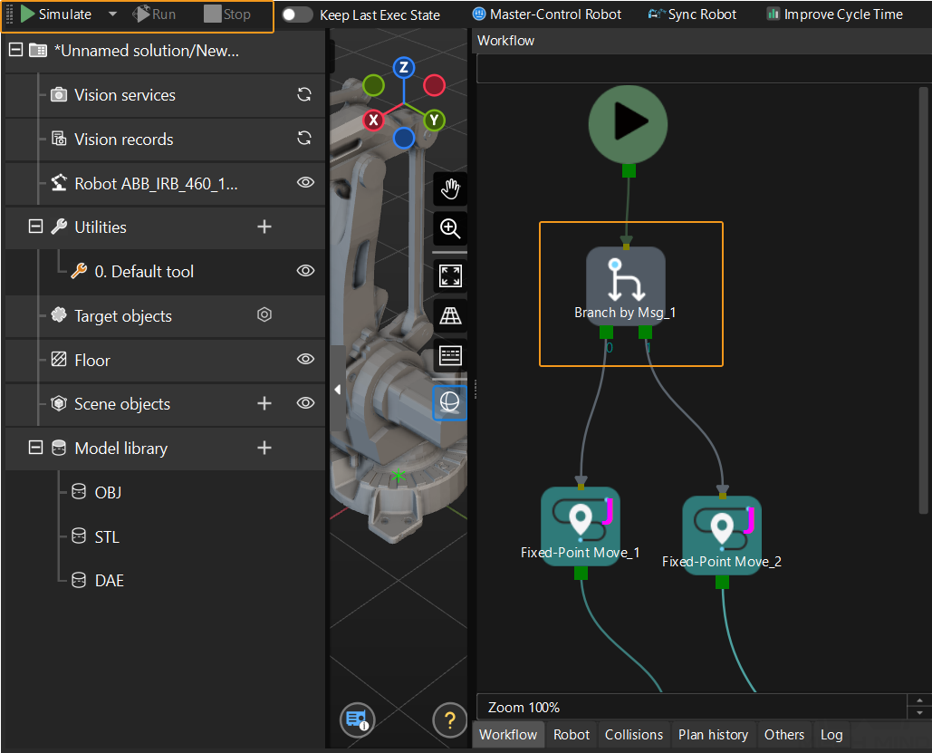
Mech-Viz: Invalid pick point
Cause:
-
None of the pick points are within the specified bin.
-
The valid tool set for the pick point in the workobject library does not match the tool selected in the Change Tool Step in the Mech-Viz project.
-
After you use the Filter Vision Result feature of the Vision Move Step, Mech-Viz will consider vision results that fall outside the specified range as invalid pick points.
Solution:
-
For the first cause:
-
Make sure that extrinsic parameters of the camera are properly set.
-
In the Output Step of the Mech-Vision project, make sure that the pose of the workobject pick point is the same as the actual workobject pose.
-
In the Vision Move Step of the Mech-Viz project, check .
-
If Update Bin with Vision is not selected, make sure that the specified bin location in the Mech-Viz project is the same as the actual bin location.
-
If Update Bin with Vision is selected, make sure that the recognized bin location in the Mech-Vision project is the same as the actual bin location.
-
-
-
For the second cause:
-
In the workobject library, check to make sure that a valid tool is configured for a pick point. For example, the valid tool for PickPoint_2 is Tool_Repositioning in the following figure.
-
Check the settings based on the operation mode selected for the Change Tool Step in the Mech-Viz project.
-
If the Operation Mode parameter of the Change Tool Step is set to Switch to specified tool, make sure that the Select Tool parameter is set to a valid tool in the tool list for the pick point.
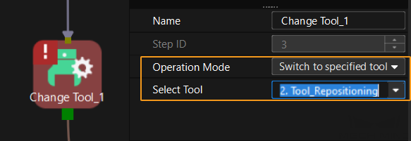
-
In the Mech-Viz project, if the Operation Mode parameter of the Change Tool Step is set to Auto-switch to appropriate tool and Limit Tools in Use is selected, make sure that the Select Tools parameter is set to valid tool in the tool list for the pick point.
-
-
-
For the third cause:
-
Modify the Mech-Vision project to ensure the vision result meets the requirements.
-
In the Vision Move Step, go to and reset the two parameters under Filter Vision Result to ensure that the pick points meet the requirements.

-
2031
Mech-Viz: Robot collision detected
For error causes and troubleshooting methods, see this description.
2032
Mech-Viz: No available placing position for palletizing
Cause:
-
The tray is full. No position is available for palletizing.
Solution:
-
Add the appropriate handling logic at the failed planning exit port of palletizing-type steps.
2036
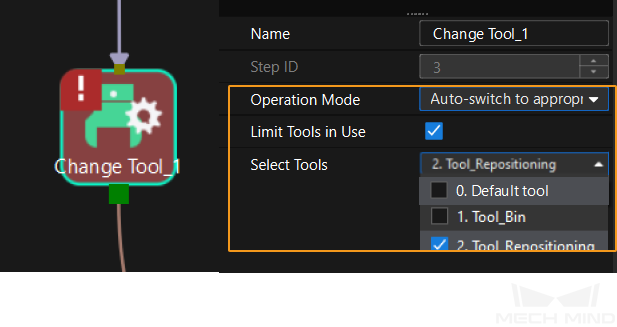
Mech-Viz: Visual Recognition Step not called
Cause:
-
The vision service set for the Vision Move Step through the Vision Service Name parameter was not successfully called. On the other hand, the Mech-Viz project was supposed to exit from the Not called” port of the Check Vision Result Step, but this port was not connected to a Step. The Mech-Viz project stopped running as a result.
Solution:
-
Check the workflow of the Mech-Viz project, and ensure that the Vision Move Step before the Check Vision Result Step is successfully called.
Vision Service indicates the name of the Mech-Vision project that corresponds to the Mech-Viz project. You can find the project name in the project list of Mech-Vision, as shown in the following figure. 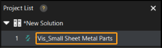
2037
Mech-Viz: No vision result received from vision service
Cause:
-
The vision service set for the Vision Move Step through the Vision Service Name parameter did not output any vision result. On the other hand, the Mech-Viz project was supposed to exit from the No result port of the Check Vision Result Step, but this port was not connected to a Step. The Mech-Viz project stopped running as a result.
Solution:
-
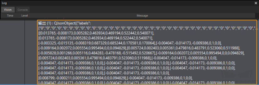
When the Mech-Viz project is running, in the Log panel of Mech-Vision, make sure that the Output Step has data, as shown in the figure below. If the Step does not contain data, see 1002 to check the entire data flow.
-
In the Mech-Viz project, make sure that the no result exit port of the Check Vision Result Step is connected to a subsequent Step, such as the Notify Step.
2038
Mech-Viz: No point cloud in ROI
Cause:
-
The vision service set for the Vision Move Step through the Vision Service Name parameter did not output any vision result. On the other hand, the Mech-Viz project was supposed to exit from the No CloudInRoi port of the Check Vision Result Step, but this port was not connected to a Step. The Mech-Viz project stopped running as a result.
Solution:
-
Refer to 1003 for troubleshooting.
2039
Mech-Viz: No vision point for the Vision Move Step
Cause:
-
Possible causes concerning the Vision Move Step are as follows:
-
The vision service did not provide vision results.
-
All poses in vision results are used up in path planning.
-
Solution:
-
Refer to 1002 for troubleshooting.
-
Check if the Check Vision Result Step is used correctly in the Mech-Viz project.
2041
Mech-Viz: Failed to get Step parameter
Cause:
-
An error occurred when the robot side sent the command to read the Mech-Viz Step parameter value.
Solution:
-
Ensure that the Step ID and parameter key name in the property_config file are correct.
| From the toolbar of Mech-Vision, go to . Click Property Configuration to open the property_config file. |
2042
Mech-Viz: Failed to get planning result in Vision Move
Cause:
-
An error occurred when the robot side sent the command to obtain Vision Move data or custom output data from Mech-Viz.
Solution:
-
Contact Mech-Mind Technical Support.
2043
Mech-Viz: Failed to get custom data
Cause:
-
An error occurred when the robot side sent the command to obtain Vision Move data or custom output data from Mech-Viz.
Solution:
-
Refer to 1024 for troubleshooting.
2044
Mech-Viz: Vision service not registered
Cause:
-
Users did not set a proper value for the Vision Service Name parameter of the Visual Recognition Step in the Mech-Viz project.
Solution:
-
Ensure that the vision service set for the Visual Recognition Step is correct.
2045
Mech-Viz: Invalid tool
Cause:
-
The Check Tool Step or the Change Tool Step failed to find the tool to check or change.
Solution:
-
Ensure that the Tool parameter set for the Check Tool Step or the Change Tool Step is valid.
2047
Mech-Viz: Check box dimensions error
-
The Mech-Vision project validated the masks of the box objects with the Validate Box Dimensions Step. However, the validation failed because the dimensions calculated from the masks did not match the data set in the Box Dimension Information in the Step Parameters panel.
Solution:
-
Check the Validate Box Dimensions Step and ensure that the input data and parameter values are correct.
Communication Component Troubleshooting
3001
Communication Component: Invalid command
Cause:
-
The vision system did not support the command sent by the robot side.
Solution:
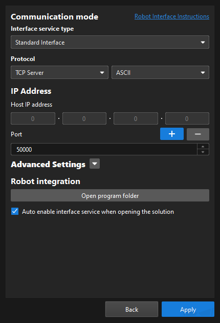
-
Check the protocol in the Robot Communication Configuration dialog box to ensure the format is correct. Also, check the protocol in the client program to make sure it matches the format set in the dialog box.
-
Check the robot program to ensure that the sent commands are correct.
3002
Communication Component: Invalid data length or format for command parameter
Cause:
-
In the command sent by the robot side, the data length was abnormal. For example, the robot pose occupied less than 6 fields.
-
In the command sent by the robot side, the data format was abnormal. For example, the Chinese comma was used as the delimiter.
Solution:
-
Check the robot program to ensure that the sent commands are correct.
3005
Communication Component: Mech-Vision timed out
Cause:
-
The vision system timed out when calling the gRPC service.
Solution:
-
Try to restart Mech-Vision.
3006
Communication Component: Unknown error
Cause:
-
Unknown error occurred in the vision system.
Solution:
-
Contact Mech-Mind Technical Support.
3007
Communication Component: Data acknowledge signal timed out
When the communication protocol is PROFINET or Ethernet/IP, the error might prompt in the following scenarios:
-
Before the vision system sent new pose data to the robot side, the robot side did not reset the Data_Acknowledge signal value to 0 within the timeout period (the value is 10s by default).
-
After the vision system sent new pose data to the robot side, the robot side did not reset the Data_Acknowledge signal value to 1 within the timeout period (the value is 10s by default).
Solution:
-
Check the robot program and ensure that the Data_Acknowledge signal value is set to 0 before the robot side sends the command to obtain vision results or obtain planned path from Mech-Viz.
-
Check the robot program and ensure that the Data_Acknowledge signal is set to 1 immediately after the program reads the pose data sent by the vision system.
3008
Communication Component: Configuration ID does not exist
Cause:
-
In the property_config file, the Config ID or parameter key name, which was used in the command sent by the robot side to read or set Mech-Viz Step parameter value, had an error.
| From the toolbar of Mech-Vision, go to . Click Property Configuration to open the property_config file. |
Solution:
-
Ensure that the Config ID and parameter key name in the property_config file are correct.
Calibration Troubleshooting
7001
Calibration: Parameter error
Cause:
-
Error occurred in the robot pose data in the command sent by the robot side to the vision system during calibration. Possible scenarios are as follows:
-
The value of the joint positions were less than 6 fields.
-
The value of the flange pose were less than 6 fields.
-
The value of the flange pose was all 0.
-
| By default, a 6-axis robot is used and thus the value of the robot pose parameter occupies six fields. If a 4-axis or 5-axis robot is used, fill in the empty fields with 0. |
Solution:
-
Ensure that the robot pose data sent by the robot side is correct.
7002
Calibration: No calibration flange pose provided from Mech-Vision
Cause:
-
During calibration, Mech-Vision did not sent the flange pose of the next calibration point to the robot.
Solution:
-
Contact Mech-Mind Technical Support.
7003
Calibration: Calibration joint positions not provided by Mech-Vision
Cause:
-
During calibration, Mech-Vision does not sent the joint positions of the next calibration point to the robot.
Solution:
-
Contact Mech-Mind Technical Support.
7004
Calibration: Robot failed to reach the calibration point
Cause:
-
During calibration, the robot failed to reach the previous calibration point. Consequently, the status code parameter value in the calibration command sent by the robot side to the vision system was 2. And the vision system did not return any data to the robot side.
Solution:
-
Contact Mech-Mind Technical Support.