Modbus TCP–MELSEC-Q Series PLC Commands
This topic introduces the commands for Modbus TCP communication between a Mitsubishi MELSEC-Q Series PLC and the Mech-Mind Vision System. For the detailed register map table, refer to another section.
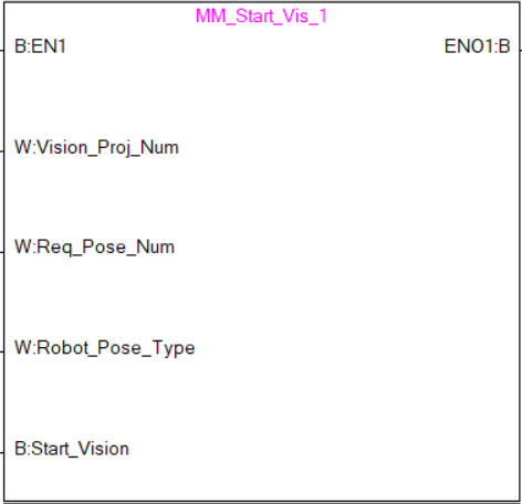
Start Mech-Vision Project
This command is used for applications that use Mech-Vision but not Mech-Viz. This command starts the Mech-Vision project that executes image capturing and performs vision recognition.
Parameters
Input parameters:
-
Vision_Proj_Num: Mech-Vision project ID, which is the number before the project name in the Project List panel in Mech-Vision.
-
Req_Pose_Num: The number of vision points that Mech-Vision is requested to send, from 1 to 20, where 0 indicates “send all”.
-
Robot_Pose_Type: The type of robot pose to input to Mech-Vision. The value range is from 0 to 3.
-
Camera_User.Robot_Pose_JPS: Joint positions of the robot. The data type is one-dimensional Array [0..5] of Real.
-
Camera_User.Robot_Pose_Flange: Flange pose of the robot. The data type is one-dimensional Array [0..5] of Real.
The following table explains the relationship between Robot_Pose_Type and Camera_User.Robot_Pose_JPS/Camera_User.Robot_Pose_Flange.
| Robot_Pose_Type | Camera_User.Robot_Pose_JPS | Camera_User.Robot_Pose_Flange | Description | Applicable Scenarios |
|---|---|---|---|---|
0 |
0, 0, 0, 0, 0, 0 |
0, 0, 0, 0, 0, 0 |
The command does not send the robot pose to the Mech-Vision project. If the Path Planning Step is used in the Mech-Vision project, the start point of the planned path will be the Home point set in the path planning tool. |
This setting should be used if the camera is mounted in eye to hand mode and the project does not require images to be captured beforehand. |
1 |
Current joint positions of the robot |
Current flange pose of the robot |
The robot joint positions and flange pose must be input to the Mech-Vision project. |
This setting should be used when the camera is mounted in eye in hand mode. This setting is recommended for most scenarios except those involving gantry robots. |
2 |
0, 0, 0, 0, 0, 0 |
Current flange pose of the robot |
The robot flange pose must be input to the Mech-Vision project. |
This setting is recommended for scenarios involving gantry robots. |
3 |
Custom joint positions of the robot |
0, 0, 0, 0, 0, 0 |
This command sends custom joint positions to the Mech-Vision project. This joint positions will be sent to the Path Planning Step in the Mech-Vision project as the start point, where the robot will move from this start point to the first waypoint of the planned path. |
This setting should be used if the camera is mounted in eye to hand mode and the project requires images to be captured beforehand. |
-
Start_Vision: Trigger the start of the Mech-Vision project at the rising edge.
Returned data from the MM_Camera global label:
-
Status_Code: 1102 is returned if no error occurred. For other values, please refer to Status Codes and Troubleshooting for the corresponding error.
Example
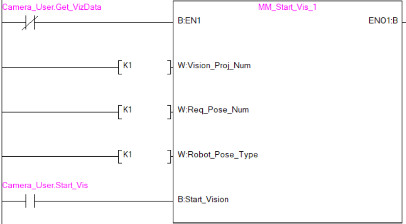
Example Description
When “Camera_User”.Start_Vis is at the rising edge, this example runs Mech-Vision project No.1, asks the Mech-Vision project to send over 1 vision point, and sends the robot joint positions when the Mech-Vision project is started as the image-capturing pose to the vision system.
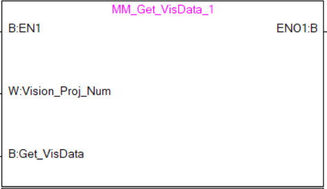
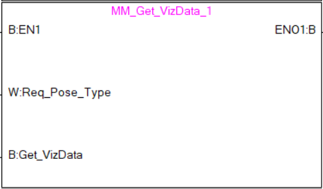
Get Vision Target(s)
This command is used for applications that use Mech-Vision but not Mech-Viz. It obtains the vision result from the corresponding Mech-Vision project.
Parameters
Input parameters:
-
Vision_Proj_Num: Mech-Vision project ID, which is the number before the project name in the Project List panel in Mech-Vision.
-
Get_VisData: Obtain vision points from Mech-Vision project when a rising edge occurs.
Returned data from the MM_Camera global label:
-
Status_Code: 1100 is returned if no error occurred. For other values, please refer to Status Codes and Troubleshooting for the corresponding error.
-
Status_of_Pose_Sent: 1 represents that the pose data written in are new. After the PLC reads the pose data, please run the MM_Empty_Target FB to reset the register to 0.
-
Number_of_Pose_Sent: Store the number of vision points sent by Mech-Vision, from 1 to 20.
-
Target_Pose: Store the waypoint poses sent by Mech-Vision as TCPs.
-
Target_Label: Store the integer labels corresponding to the poses. Labels are set in Mech-Vision.
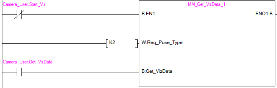
Example
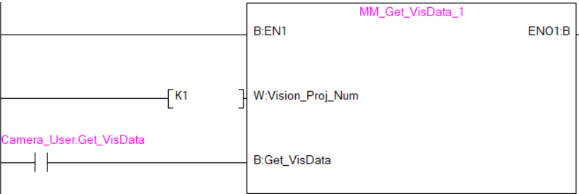
Example Description
When Camera_User.Get_VisData is at the rising edge, this example obtains the vision result from Mech-Vision project No. 1.
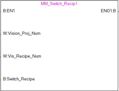
Switch Mech-Vision Recipe
This command specifies which parameter recipe of the Mech-Vision project to use. Parameter recipes can be used to switch parameter settings, including point cloud model for matching, ROI, confidence threshold, etc, in the same Mech-Vision project when it is used to recognize different workpieces. This command must be called BEFORE MM_Start_Vis.
Parameters
Input parameters:
-
Vision_Proj_Num: Mech-Vision project ID, which is the number before the project name in the Project List panel in Mech-Vision.
-
Vision_Recipe_Num_O: The ID of a parameter recipe in the Mech-Vision project, from 1 to 99.
-
Switch_Recipe: Trigger to switch the parameter recipe at the rising edge.
Returned data from the MM_Camera global label:
-
Status_Code: 1107 is returned if no error occurred. For other values, please refer to Status Codes and Troubleshooting for the corresponding error.
Example
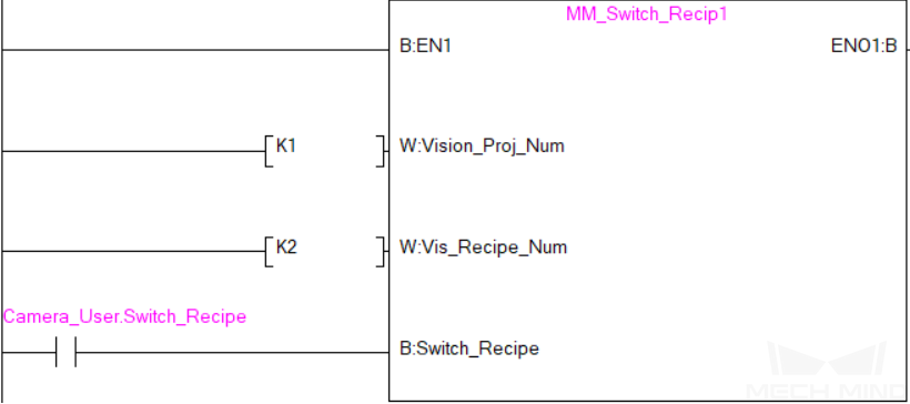
Example Description
When Camera_User.Switch_Recipe is at the rising edge, this example switches the parameter recipe used to No. 2 in Mech-Vision project No. 1.
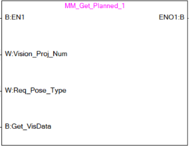
Get Result of Step “Path Planning” in Mech-Vision
After calling MM_Start_Vis, call this command to obtain the collision-free picking path planned by the “Path Planning” Step in the Mech-Vision project.
When using this command, set the Port Type parameter of the “Output” Step in the Mech-Vision project to “Predefined (robot path)”.
| Before executing this command, please set Req_Pose_Num in MM_Start_Vis to 0 to reduce the times of execution of this command. If Req_Pose_Num in MM_Start_Vis is set to 1, then every time this command is executed, only 1 waypoint is returned, and this command must be executed multiple times to obtain all the waypoints. |
Parameters
Input parameters:
-
Vision_Proj_Num: Mech-Vision project ID, which is the number before the project name in the Project List panel in Mech-Vision.
-
Request_Pose_Type: This parameter specifies the type of waypoint poses returned by the “Path Planning” Step.
-
1: The waypoint poses are returned in the form of joint positions. -
2: The waypoint poses are returned in the form of TCP.
-
| The Request_Pose_Type here and the Robot_Pose_Type in the MM_Start_Vis and MM_Start_Viz FBs all correspond to the same Pose Type label in the MM Modbus TCP Interface data block. Therefore, if these parameters are set to different values, the programming should ensure that the two values do not take effect at the same time. |
-
Get_VisData: Obtains the planned path from the “Path Planning” Step in Mech-Vision at the rising edge.
Returned data from the MM_Camera global label:
-
Status_Code: 1103 is returned if no error occurred. For other values, please refer to Status Codes and Troubleshooting for the corresponding error.
-
Status of Pose Sent: 1 represents that the pose data written in are new. After the PLC reads the pose data, please run the MM_Empty_Target FB to reset the register to 0.
-
Number of Pose Sent: Store the number of received waypoints sent by Mech-Vision, from 1 to 20.
-
Index_of_Vision_Picking_Point: The position of the Vision Move waypoint in the entire robot motion path.
-
Target_Pose: Store the received waypoint poses in the form of joint positions or the XYZ Euler angles, depending on the input parameter Request_Pose_Type.
-
Target_Label: Store the integer labels corresponding to the poses. Labels are set in Mech-Vision.
-
Target_Tool_ID: The tool ID specified in the path planning tool.
Example
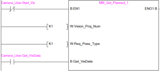
Example Description
When Camera_User.Get_VisData is at the rising edge, this example obtains the planned path from Mech-Vision No.1 in the form of joint positions.
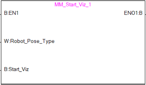
Start Mech-Viz Project
This command is for applications that use both Mech-Vision and Mech-Viz. It runs the corresponding Mech-Viz project (which triggers the corresponding Mech-Vision project to run), and then plans the path for picking.
Parameters
Input parameters:
-
Robot_Pose_Type: The robot pose type specifies the type of the pose of the real robot to be input to the Mech-Viz project. The value range is from 0 to 2.
-
Camera_User.Robot_Pose_JPS: Current joint positions of the robot. The data type is one-dimensional Array [0..5] of Real.
-
Camera_User.Robot_Pose_Flange: Current flange pose of the robot. The data type is one-dimensional Array [0..5] of Real.
The following table explains the relationship between Robot_Pose_Type and Camera_User.Robot_Pose_JPS/Camera_User.Robot_Pose_Flange.
| Robot_Pose_Type | Camera_User.Robot_Pose_JPS | Camera_User.Robot_Pose_Flange | Description | Applicable Scenarios |
|---|---|---|---|---|
0 |
0, 0, 0, 0, 0, 0 |
0, 0, 0, 0, 0, 0 |
No need to input the robot pose to Mech-Viz. The simulated robot in Mech-Viz moves from the initial pose JPs = [0, 0, 0, 0, 0, 0] to the first waypoint. |
Project is in the eye-to-hand mode. This setting is not recommended. |
1 |
Current joint positions of the robot |
Current flange pose of the robot |
Robot joint positions and flange pose must be input to Mech-Viz. The simulated robot in Mech-Viz moves from the input JPs to the first waypoint. |
This setting is recommended for projects in the eye-in-hand mode. |
2 |
Specific joint positions of the robot |
0, 0, 0, 0, 0, 0 |
The robot joint positions of a point determined by teaching must be input to Mech-Viz. The input joint positions are used to trigger Mech-Viz to plan the next path in advance while the robot is not in the camera capture region, as shown below. The simulated robot in Mech-Viz moves from the input joint positions to the first waypoint. |
This setting is recommended for projects in the eye-to-hand mode. |
|
The reason for setting Robot_Pose_Type to 2 when the project is in the eye-to-hand mode:
In the eye-to-hand mode, the camera can perform image capturing for the next round of path planning before the robot returns to the camera capture region and picking region, shortening the cycle time. If Robot_Pose_Type is set to 1, the robot’s current pose is sent to Mech-Viz. The simulated robot will move from the input pose to the first waypoint in the planned path, while the real robot might move to another point first, and then move to the first waypoint. Therefore, the path of the real robot may contain unpredicted collisions, leading to safety hazards. In conclusion, Robot_Pose_Type should be set to 2 for projects in the eye-to-hand mode. 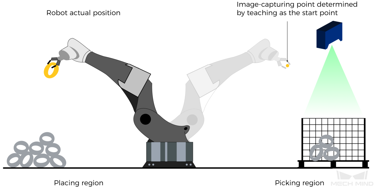
|
-
Start_Viz: Triggers Mech-Viz project to run at the rising edge.
Returned data from the MM_Camera global label:
-
Status_Code: 2103 is returned if Mech-Viz is successfully started and no error occurred. For other values, please refer to Status Codes and Troubleshooting for the corresponding error.
Example
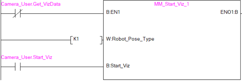
Example Description
When the label Camera_User.Start_Viz is at the rising edge, this example runs the corresponding Mech-Viz project, and sends the current joint positions of the robot to the vision system.
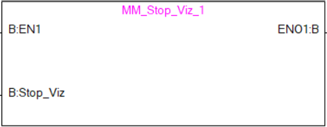
Stop Mech-Viz Project
This command is used to stop Mech-Viz project. This command is only needed if the Mech-Viz project falls into an infinite loop or cannot be stopped normally.
Parameters
Input parameters:
-
Stop_Viz: Stop the execution of the Mech-Viz project at the rising edge.
Returned data from the MM_Camera global label:
-
Status_Code: 2104 is returned if Mech-Viz is successfully stopped and no error occurred. For other values, please refer to Status Codes and Troubleshooting for the corresponding error.
Example
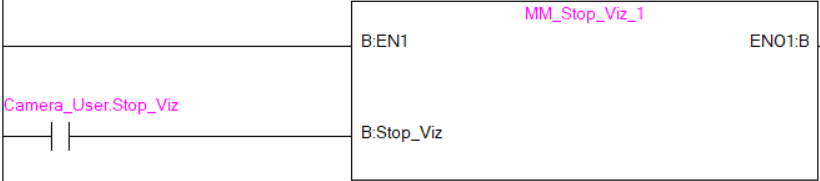
Example Description
When Camera_User.Stop_Viz is at the rising edge, this example stops the execution of the Mech-Viz project.
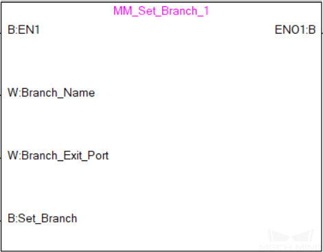
Select Mech-Viz Branch
This command is used to select along which branch the Mech-Viz project should proceed. Such branching is achieved by adding Branch by Msg Step(s) to the Mech-Viz project. This command specifies which exit port such Step(s) should take. MM_Start_Viz should be called BEFORE this subprogram. When executing the “Branch by Msg” Step, Mech-Viz waits for the exit port No. sent by Command 203.
Parameters
Input parameters:
-
Branch_Name: Step ID of the Branch by Msg Step, which is a positive integer.
-
Branch_Exit_Port: The number of the exit port to take, from 1 to 99.
Add 1 to the port number displayed in Mech-Viz. E.g., value 1 corresponds to exit port 0 in Mech-Viz. -
Set_Branch: Set the branch to take at the rising edge.
Returned data from the MM_Camera global label:
-
Status_Code: 2105 is returned if the branch is successfully selected and no error occurred. For other values, please refer to Status Codes and Troubleshooting for the corresponding error.
Example
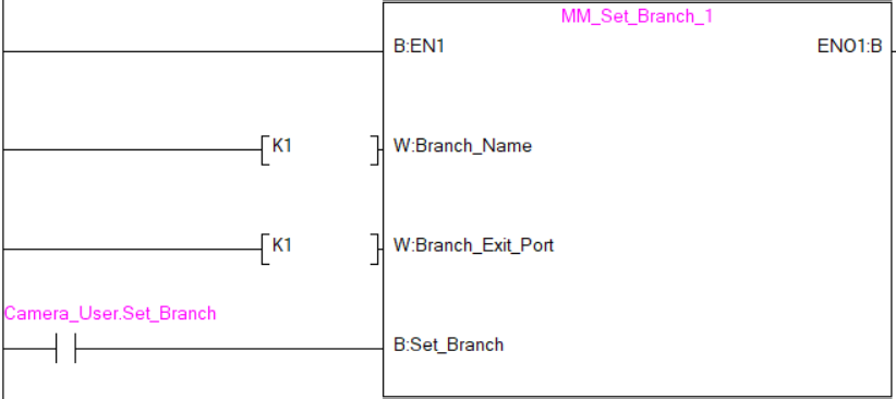
Example Description
When Camera_User.Set_Branch is at the rising edge, this example tells Mech-Viz to take exit port 1 for the Branch by Msg Step whose Step ID is 1.
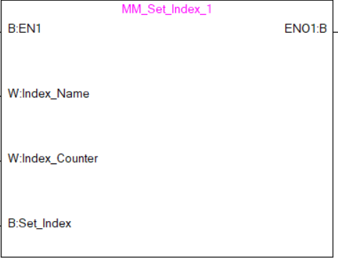
Set Move Index
This command sets the value for the Current Index parameter of Steps. Steps that have this parameter include Move by List, Move by Grid, Custom Pallet Pattern, and Smart Pallet Pattern. MM_Start_Viz must be called BEFORE this command.
Parameters
Input parameters:
-
Index_Name: Step ID of the Step with the index parameter, which is a positive integer.
-
Index_Counter: The index value that should be set the next time this Step is executed. When this command is sent, the current index value in Mech-Viz will become the parameter value minus 1. When the Mech-Viz project runs to the Step specified by this command, the current index value in Mech-Viz will be increased by 1 to become the parameter’s value.
-
Set_Index: Trigger signal to set the index. The rising edge does the trigger.
Returned data from the MM_Camera global label:
-
Status_Code: 2106 is returned if the index is successfully set and no error occurred. For other values, please refer to Status Codes and Troubleshooting for the corresponding error.
Example
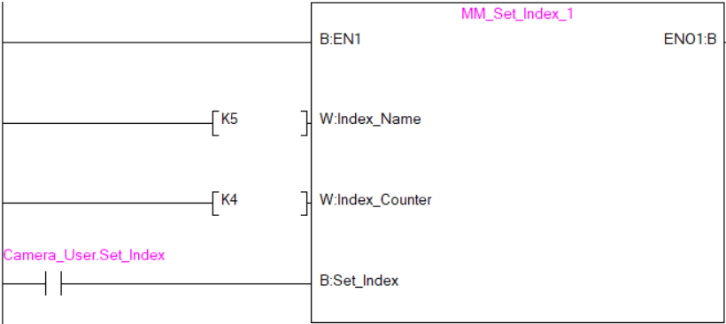
Example Description
When Camera_User.Set_Index is at the rising edge, this example sets the Current Index value to 3 for the Step whose Step ID is 5. When the Step is executed, the Current Index value will be added 1 and become 4.
Get Planned Path
This command obtains the planned path from Mech-Viz.
Parameters
Input parameters:
-
Request_Pose_Type: Pose type of the waypoints to be obtained.
-
1: Mech-Viz sends waypoints in joint positions.
-
2: Mech-Viz sends waypoints in TCPs.
-
| The Request_Pose_Type here and the Robot_Pose_Type in the MM_Start_Vis and MM_Start_Viz FBs all correspond to the same Pose Type label in the MM_Camera global label. Therefore, if these parameters are set to different values, the programming should ensure that the two values do not take effect at the same time. |
-
Get_VizData: Obtains the planned path from Mech-Viz at the rising edge.
Returned data from the MM_Camera global label:
-
Status_Code: 2100 is returned if no error occurred. For other values, please refer to Status Codes and Troubleshooting for the corresponding error.
-
Status_of_Pose_Sent: 1 represents that the pose data written in are new. After the PLC reads the pose data, please run the MM_Empty_Target FB to reset the register to 0.
-
Number_of_Pose_Sent: Store the number of waypoints received from Mech-Viz, from 1 to 20.
-
Index_of_Vision_Picking_Point: The position of the Vision Move waypoint in the entire robot motion path.
-
Target_Pose: Store the received waypoint poses in the form of joint positions or the XYZ Euler angles, depending on the pose type set by Command 205.
-
Target_Label: Store the integer labels corresponding to the poses. Labels are set in Mech-Vision.
-
Target_Tool_ID: The tool ID specified in the Mech-Viz project.
Example
Example Description
When “Camera_User”.Get_VizData is at the rising edge, this example obtains the planned path from Mech-Viz in the form of TCPs.
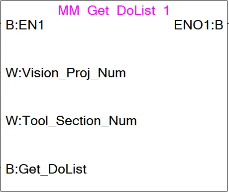
Get DO Signal List
This command obtains the control signal list for the multi-section vacuum gripper from the Mech-Vision or Mech-Viz project. Before calling this command, please call MM_Get_Planned or MM_Get_VizData.
Before using this command, you must perform the following configurations in Mech-Vision or Mech-Viz.
-
Configure the Mech-Vision project
-
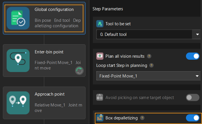
In the Path Planning Step, click Config wizard. In Global configuration, enable Box depalletizing.
-
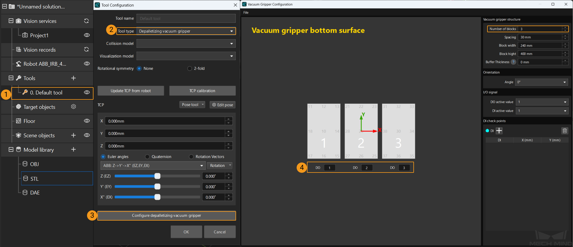
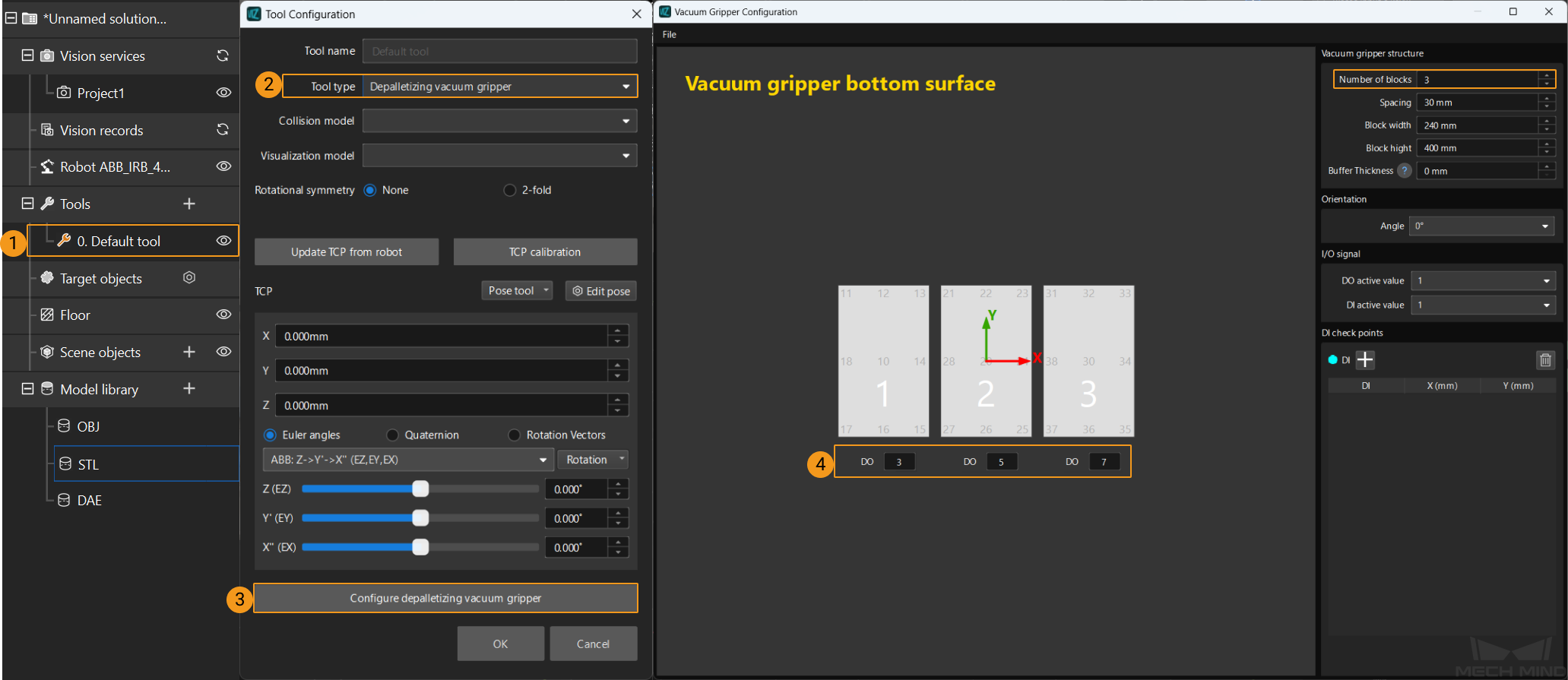
In the Path Planning Step, click Config wizard, and then double-click the name of the robot tool. In the pop-up window, select Depalletizing vacuum gripper for Tool type, click Configure depalletizing vacuum gripper, and then configure DO signals according to needs.
-
-
Configure the Mech-Viz project
-
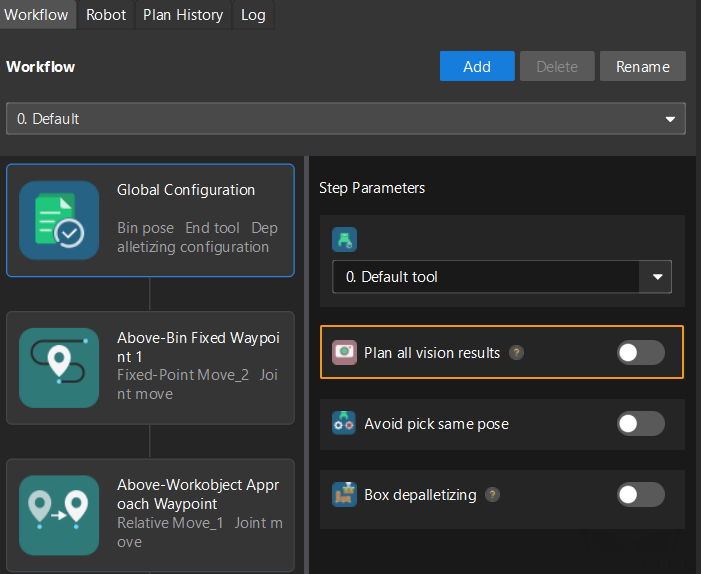
In the Vision Move Step of Mech-Viz, set Select Picking Method to Box depalletizing.

-
In Mech-Viz, double-click the tool name, select Depalletizing vacuum gripper for Tool type, click Configure depalletizing vacuum gripper, and then configure the DO signals according to needs.
-
Parameters
Input parameters:
-
Vision_Proj_Num: This parameter specifies the source of the DO signal list. Value range: 0 to the largest positive integer.
-
0: Get DO signal list from Mech-Viz.
-
A positive integer: Get DO signal list from Mech-Vision. The positive integer is the Mech-Vision project ID.
-
-
Tool_Section_Num: This parameter indicates the number of vacuum gripper sections.
-
Get_DoList: The trigger to obtain the planned DO signal list at the rising edge.
Returned data from the MM_Camera global label:
-
Status_Code: 2102 is returned if the DO signal list is successfully obtained and no error occurred. For other values, please refer to Status Codes and Troubleshooting for the corresponding error.
-
DO_LIST: The list of 64 DO values, in the range of 0 to 999, with -1 being the placeholder value.
The DO signals returned by this command vary based on the deployed project.
-
Gripper DO signals planned by the Mech-Vision project
-
Under Global Configuration of the path planning tool, if Plan all vision results is disabled, this command returns 64 gripper DO signals that are planned in this round. Valid DO signals are non-negative integers ranging from 0 to 999. Invalid DO signals are -1, which serves as a placeholder.
For example, valid DO signals in the table below are 1, 3, 5, and 6, which means that the robot will set the values of these DO signals to ON.
1st
2nd
3rd
4th
5th
6th
7th
8th
…
63rd
64th
1
3
5
6
-1
-1
-1
-1
…
-1
-1
-
Under Global Configuration of the path planning tool, if Plan all vision results is enabled, Mech-Vision can perform multiple rounds of planning based on the same vision result. The 64 gripper DO signals returned by this command are obtained during all rounds of planning. In this case, you can use the number of vacuum gripper sections to differentiate the gripper DO signals obtained during each round of planning.
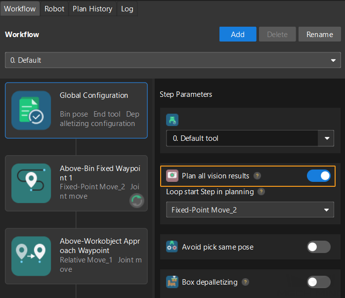
For example, if the number of vacuum gripper sections is 4 and the command returns 64 DO signals in total, each 4 DO signals are multi-section vacuum gripper signals obtained during each round of planning.
First round of planning
Second round of planning
…
16th round of planning
1st
2nd
3rd
4th
5th
6th
7th
8th
…
61st
62nd
63rd
64th
1
3
4
-1
1
4
-1
-1
…
-1
-1
-1
-1
-
-
Gripper DO signals planned by the Mech-Viz project
-
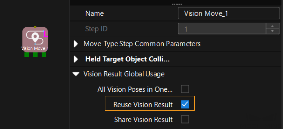
If Reuse Vision Result is not selected for the Vision Move Step, this command returns 64 gripper DO signals that are planned during this round. Valid DO signals are non-negative integers ranging from 0 to 999. Invalid DO signals are -1, which serves as a placeholder.
For example, valid DO signals in the table below are 1, 3, 5, and 6, which means that the robot will set the values of these DO signals to ON.
1st
2nd
3rd
4th
5th
6th
7th
8th
…
63rd
64th
1
3
5
6
-1
-1
-1
-1
…
-1
-1
-
If Reuse Vision Result is selected for the Vision Move Step and the Vision Move Step is used in a loop, Mech-Viz can perform multiple rounds of planning based on the same vision result. The 64 gripper DO signals returned by this command are obtained during all rounds of planning. In this case, you can use the number of vacuum gripper sections to differentiate the gripper DO signals obtained during each round of planning.
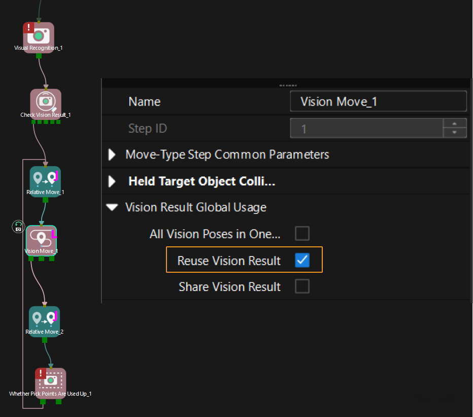
For example, if the number of vacuum gripper sections is 4 and the command returns 64 DO signals in total, each 4 DO signals are multi-section vacuum gripper signals obtained during each round of planning.
First round of planning
Second round of planning
…
16th round of planning
1st
2nd
3rd
4th
5th
6th
7th
8th
…
61st
62nd
63rd
64th
1
3
4
-1
1
4
-1
-1
…
-1
-1
-1
-1
-
Example
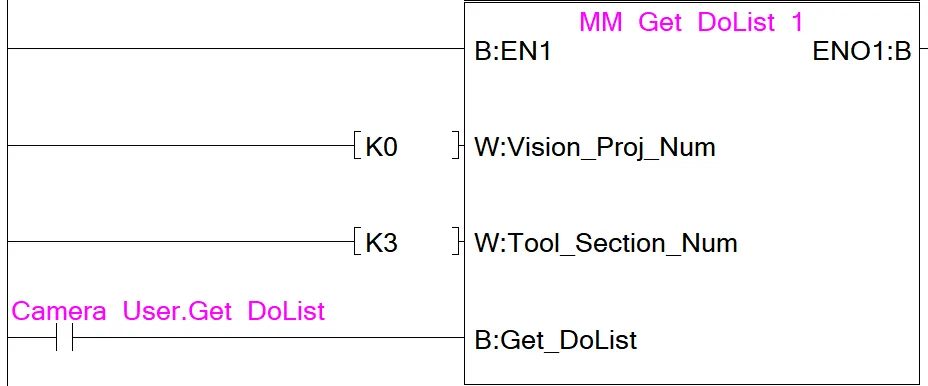
Example Description
In this example, when a rising edge is detected for the Camera_User.Get_DoList label, if Vision_Proj_Num is 0 and Tool_Section_Num is 3, the DO signal list returned by Mech-Viz will be saved to the DO array.
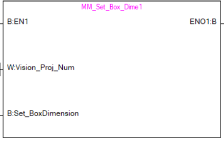
Input Object Dimensions to Mech-Vision
This command inputs object dimensions to the Mech-Vision project.
Parameters
Input parameters:
-
Vision_Proj_Num: The Project ID of the Mech-Vision project; you can check the project ID before the project name in the Project List panel in Mech-Vision.
-
Label Camera_User.External_Input_Box_Dimension: The 3D dimensions (in mm) to be input to the project, as an array of 3 real numbers.
-
Set_Box_Dimension: Input the object dimensions to the Read Object Dimensions Step in the Mech-Vision project at the rising edge.
Returned data from the MM_Camera global label:
-
Status_Code: 1108 is returned if no error occurred. For other values, please refer to Status Codes and Troubleshooting for the corresponding error.
Example
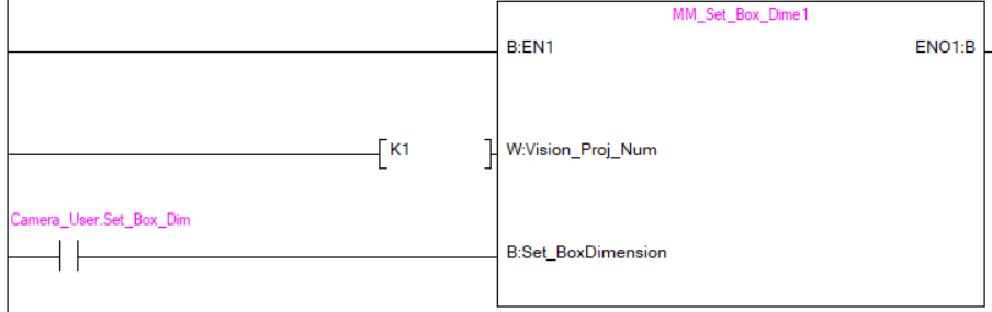
Example Description
When Camera_User.Set_Box_Dimension is at the rising edge, this example sets the object dimensions in the Read Object Dimensions Step in the Mech-Vision project No. 1 to the values in External_Input_Box_Dimension.
Get Software Status
This command is currently capable of checking whether Mech-Vision ready to run projects. In the future, this command can be used for obtaining the software execution status.

Parameters
Input parameters:
-
Get_Status: Check whether Mech-Vision is ready to run projects at the rising edge.
Returned data from the MM_Camera global label:
-
Status code: Represent the software status.
Example
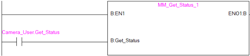
Example Description
When Camera_User.Get_Status is at the rising edge, this example checks the status code and stores it in the FromCamera.STATUS_CODE.
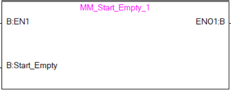
Clear Target Data
This command clears the obtained data stored in Target_Pose, Target_Label, and Target_Tool_ID.
Parameters
Input parameters:
-
Start_Empty: Clear the obtained data stored in Target_Pose, Target_Label, and Target_Tool_ID.This variable will take effect when it is set to 1.
Returned data from the MM_Camera global label:
-
Status_Code: 3103 is returned if no error occurred. For other values, please refer to Status Codes and Troubleshooting for the corresponding error.
-
Target_Pose: Obtained waypoint poses.
-
Target_Label: Obtained labels.
-
Target_Tool_ID: The obtained tool ID.
Example

Example Description
When the Camera_User.Start_Empty label is set, the data stored in Target_Pose, Target_Label, and Target_Tool_ID are cleared.
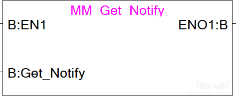
Get Message from Notify Step
After the Mech-Vision or Mech-Viz project is triggered, this command can be called to get message from the “Notify” Step.
| When the “Notify” Step is executed in the Mech-Vision or Mech-Viz project, the message remains in the buffer of the vision system for only 1 second. Therefore, users should consider the timing of calling this command to ensure successful message retrieval. Additionally, the register that stores the message will be cleared next time the Mech-Vision or Mech-Viz project runs. |
Parameters
Input parameters:
-
Get_Notify: Get a message from the “Notify” Step, triggered at a rising edge.
Returned data from the MM_Camera global label:
-
Notify: The message from the Notify Step, which is an integer.
Example
For example, the message set in the “Notify” Step is 777, and the PLC is obtaining a message in the automatic mode.
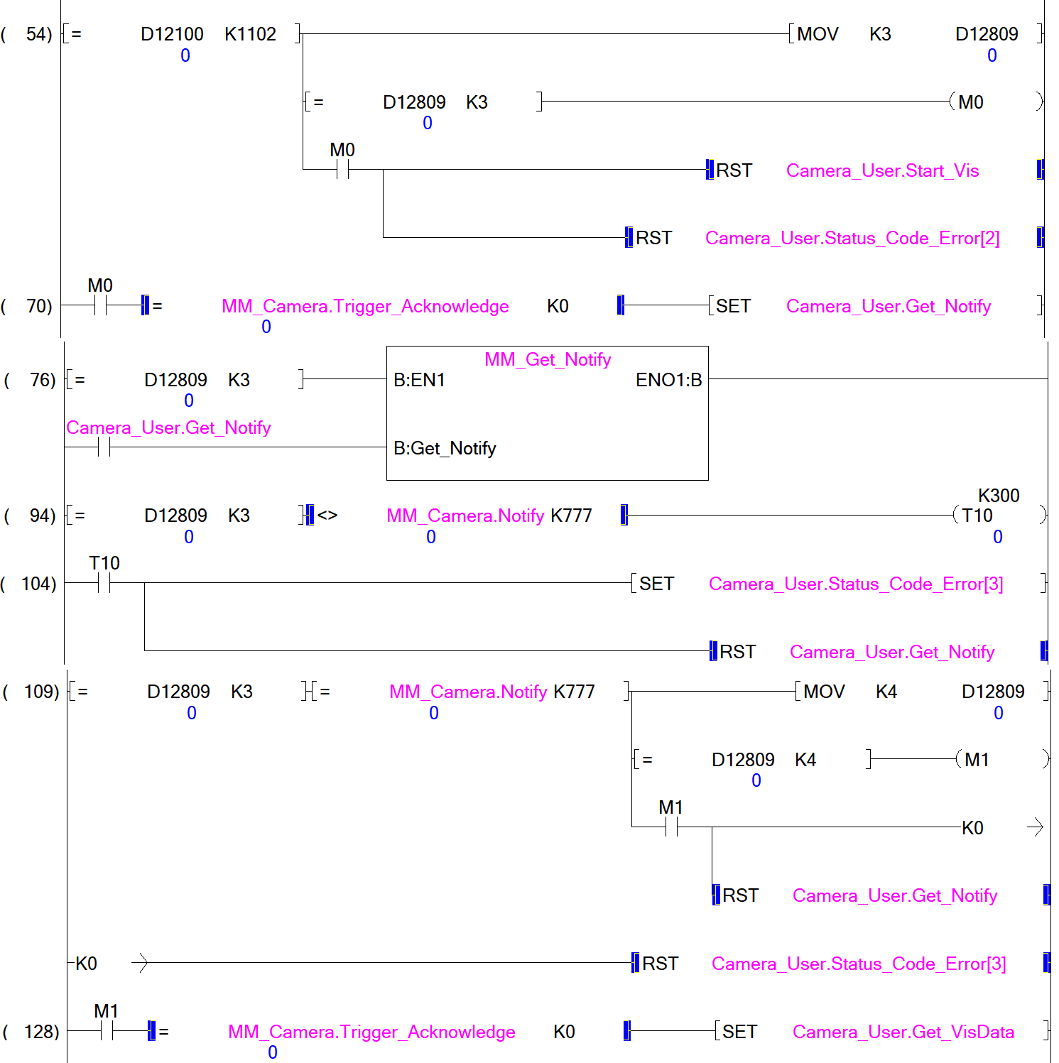
Example Description
In this example, when D12809 (namely, Camera_User.Step_Num) is set to 3 in the automatic mode, the value of MM_Camera.Notify is not 777. After the MM_Get_Notify command is enabled when the Camera_User.Get_Notify variable is at the rising edge, the program retrieves the a message from the “Notify” Step. If the message retrieval was successful, the value of MM_Camera.Notify changes to 777. Otherwise, if the value remains unchanged, the PLC will prompt an error after 3 seconds.
Description of the Status Codes
Please refer to Status Codes and Troubleshooting for detailed information.