Communication Configuration and Example Program Usage (PLC with Built-in Ethernet Port)
This topic provides instructions on setting up the Standard Interface communication based on the MC protocol between a Mitsubishi MELSEC iQ-R Series PLC (with Built-in Ethernet Port) and the Mech-Mind Vision System.
| The communication protocol used here is Seamless Message Protocol (SLMP). The 3E frame of SLMP has the same message format as the 3E frame of the QnA series in the MC protocol. Therefore, devices using the 3E frame of the QnA series in the MC protocol (such as the vision system) can communicate with Mitsubishi iQ-R series PLCs by using SLMP. |
Hardware and Software Requirements
Hardware
-
Mitsubishi iQ-R Series PLC: with built-in Ethernet Port
In this example, the CPU series used is RCPU, the model is R00, the power module is R61P, and the base unit is R33B.
-
An IPC and a computer
-
USB Type A male to USB Mini-B male cable (used to download PLC programs)
-
Ethernet cable (used to connect the IPC and the PLC)
Software
| Software | Description | Installed location |
|---|---|---|
GX Works3 1.081K |
Mitsubishi PLC programming software |
Computer that is used for PLC sequence programming |
Mech-Vision and Mech-Viz |
Mech-Mind Vision System |
IPC |
In addition to the above software, please copy the iQ-R_SLMP.usl file (used to implement the features of various interface commands) to a computer that has with GX Works3 installed. The example program file can be found by using the Communication Component/Robot_Interface/Mitsubishi MC path in the folder where Mech-Vision and Mech-Viz are installed.
| The firewall on the IPC or computer must be turned off. |
Create and Configure the PLC Project
Create a PLC Project
-
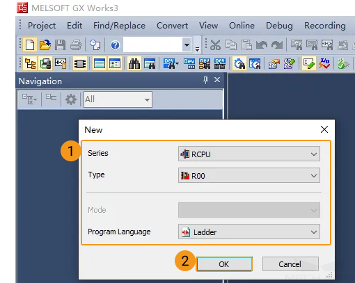
Open GX Works3, click the New icon in the toolbar. In the New dialog box, select RCPU for Series, R00 for Type, and Ladder for Program Language, and then click OK.
-
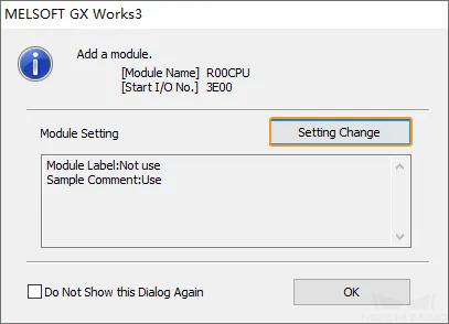
In the dialog box that appears, click Settings Change.
-
In the dialog box that appears, select Yes for Use Module Label in the Operation Setting section and then click OK. Return to the previous dialog box and click OK.
-
Go to on the left and then double-click Connection.
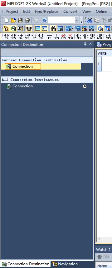
-
In the Specify Connection Destination Connection dialog box, complete the following configurations.
-
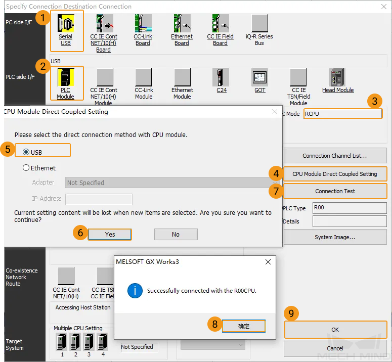
Select Serial USB in the PC side section, select PLC Module in the PLC side section, confirm that the CPU type is RCPU, and then click CPU Module Direct Coupled Setting.
-
Select USB in the pop-up dialog box and click Yes.
-
Return to the Specify Connection Destination Connection dialog box and click Connection Test. If the connection between GX Works3 and the PLC is established successfully, the Successfully connected with the R00CPU message will appear.
-
Click OK in the Specify Connection Destination Connection dialog box and go back to the main interface of GX Works3.
-
-
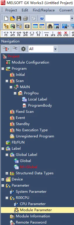
In the left-side navigation pane of the main interface of GX Works3, perform the following operations.
-
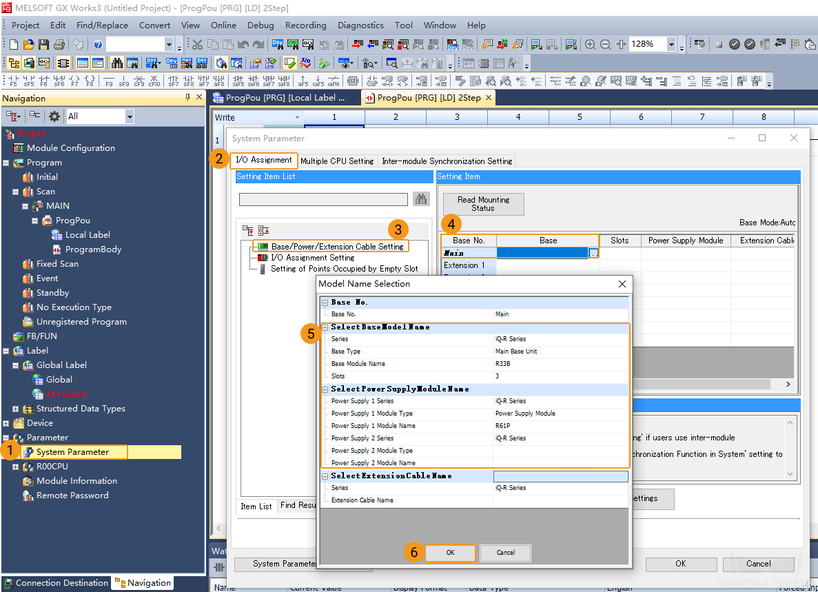
Navigate to Parameter and double-click System Parameter.
-
In the System Parameter dialog box, click the I/O Assignment tab, select Base/Power/Extension Cable Setting, and then click ... next to .
-
In the Model Name Selection dialog box, select the base module and power supply model based on actual situation and then click OK. In this example, R33B and R61P are selected.
-
In the following dialog box, click OK. Return to System Parameter dialog box and click OK.
-
Configure SLMP Communication Parameters
-
Go to , double-click Module Parameter.
-
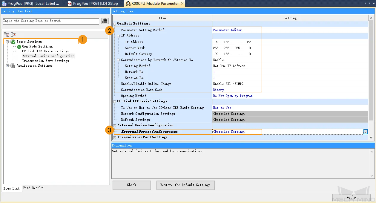
In the R00CPU Module Parameter dialog box, click Basic Settings.
-
In the IP Address section, specify the IP address settings of the PLC. In this example, the IP address is 192.168.1.22, the subnet mask is 255.255.255.0, and the default gateway is 192.168.1.0. The IP address of the PLC and that of the IPC must reside in the same subnet.
-
Select Enable for Communication by Network No./Station No., select Not Use IP Address for Setting Method, and then set Network No. and Station No. to 1.
-
Set Enable/Disable Online Change to Enable All (SLMP).
-
Set Communication Data Code to Binary.
-
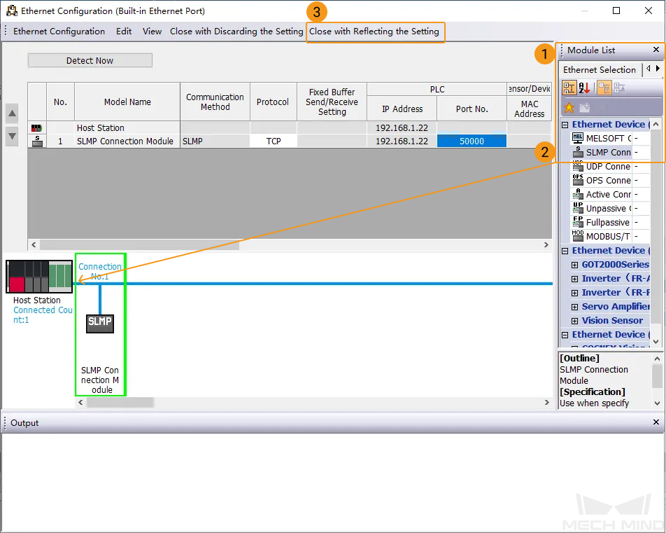
Click ... next to . The Ethernet Configuration (Built-in Ethernet Port) dialog box will appear.
In the Module List section on the right, select , drag SLMP Connection Module to Host Station, set the parameters in the first line based on the following figure, and then click Close with Reflecting the Setting. Return to the R00CPU Module Parameter dialog box, click Apply, and then return to the main interface of GX Works3.
-
Import Example Programs
| Before you add an example program to a project already in use, it is recommended to import it to a new project and test it first. |
-
In the menu bar of GX Works3. Select .
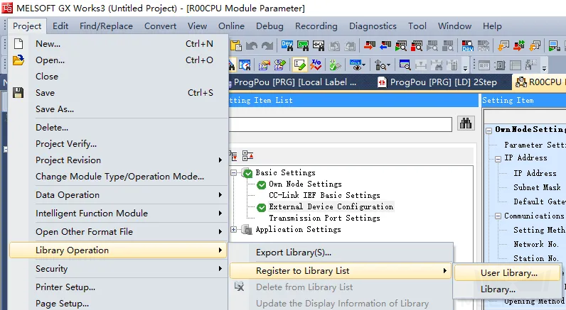
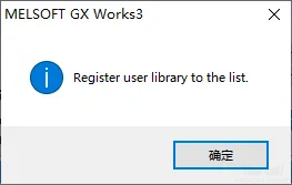
In the dialog box where “Register user library to the list” is displayed, click OK.
-
In the Register Library to Library List dialog box, find the
iQ-R_SLMP.uslfile (which needs to be copied from the IPC in advance) and click Open.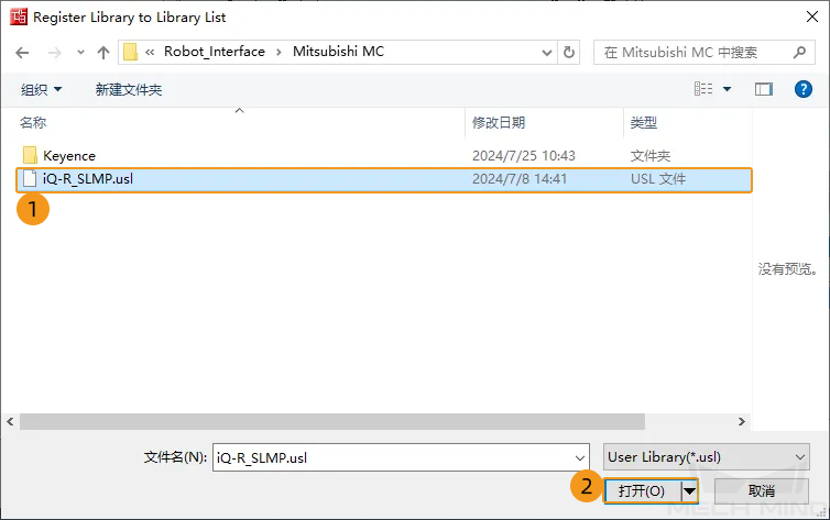
-
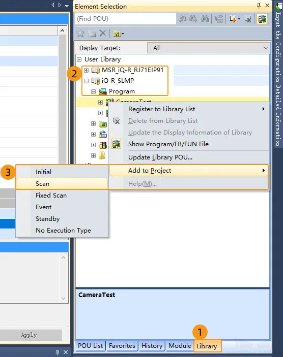
In the Element Selection section on the right of the main interface of GX Works3, click the Library tab, select , and then right-click to select .
-
In the dialog box that asks whether to overwrite data, click Yes, and then return to the main interface of GX Works3.

-
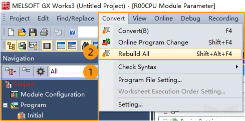
In the Navigation section, check to make sure that the programs, FBs, and labels in the Project section are imported. Select in the menu bar. The Rebuild All dialog box will appear.
-
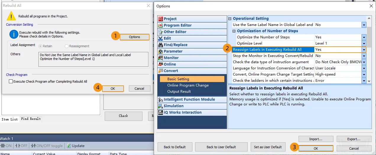
In the Rebuild All dialog box, perform the following operations.
-
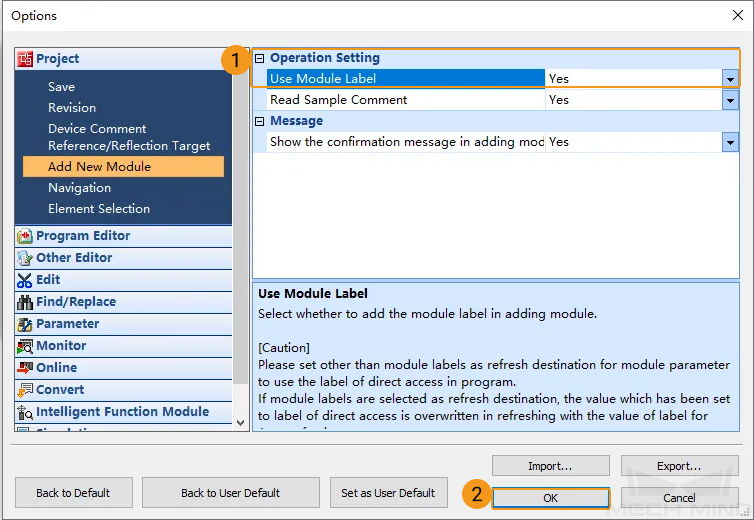
Click Options. The Options dialog box will appear.
-
Go to , set Reassign Labels in Executing Rebuild All to Yes, and then click OK.
-
Return to the Rebuild All dialog box and click OK.
-
Download Communication Configuration and Example Programs to PLC
-
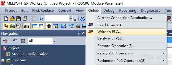
After the program is converted successfully, select in the menu bar.
-
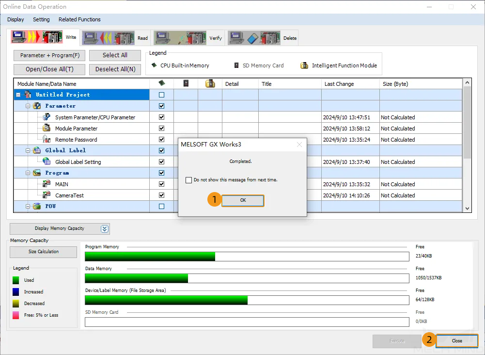
In the Online Data Operation dialog box, select .
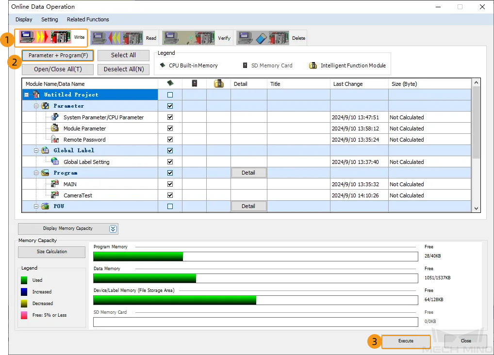
-
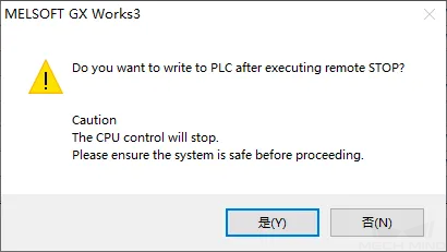
In the dialog box that asks whether to write and provides precautions, click Yes.
-
If the safety can be ensured, select Yes.
-
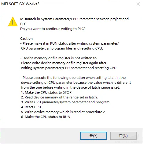
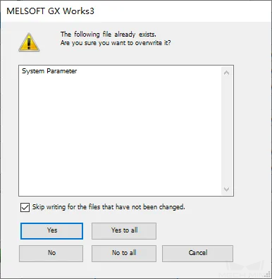
In the dialog box that asks whether to overwrite system parameters, click Yes.
-
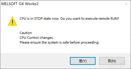
After the download is successful, the dialog box that asks whether to execute remote run will appear. If the safety can be ensured, select Yes.
-
In the Completed dialog box, click Yes after ensuring the safety. Go back to the Online Data Operation dialog box and click Close. The settings will take effect after the PLC is powered off and then powered on.
Set up “Robot Communication Configuration”
-
Click Robot Communication Configuration on the toolbar of Mech-Vision.
-
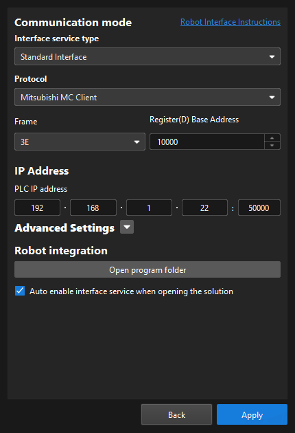
In the Robot Communication Configuration window, complete the following configurations.
-
Click the Select robot drop-down menu, and select Listed robot. Click Select robot model, and select the robot model that you use. Then, click Next.
-
In the Communication mode area, select Standard Interface for Interface service type, Mitsubishi MC Client for Protocol, and 3E for Frame. Users can set Register(D) Base Address according to actual needs. The value is set to 10000 in this example. In addition, the MM_Interface structure occupies 1528 D Registers in total.
-
In the PLC IP address text box, enter the IP address and port number of the specific PLC in use.
-
(Optional) Select Auto enable interface service when opening the solution.
-
Click Apply.
-
-
On the main interface of Mech-Vision, make sure that the Robot Communication Configuration switch on the toolbar is flipped and turned to blue.

Check Communication
-
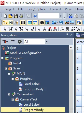
In the Navigation section, go to , and then double-click ProgramBody.
-
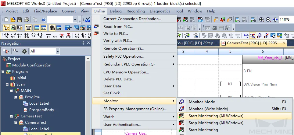
Select in the menu bar.
-
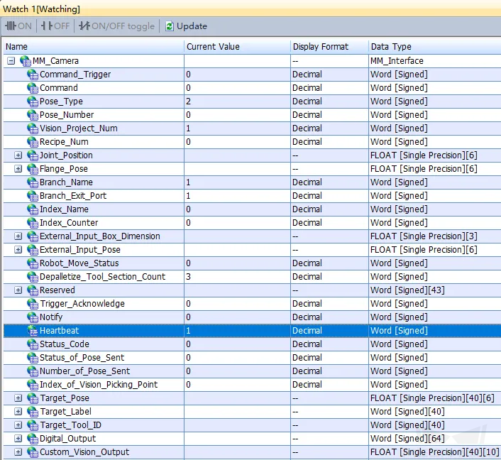
In the Watch1 dialog box, add and expand the MM_Camera. If the connection is established successfully, the value of Heartbeat will keep changing.
-
The PLC is successfully connected if the following message is displayed in the Console tab of Mech-Vision Log panel: Connect to Melsec PLC successfully.
If you don’t see this log message, please check if:
-
The hardware network connection is normal.
-
The Robot Communication Configuration option on the toolbar of Mech-Vision is enabled.
-
The PLC program is downloaded to the PLC.
-
Test with Mech-Vision/Mech-Viz Project
This section introduces how to use the example program FB to trigger the Mech-Vision project to run and obtain the vision result and trigger the Mech-Viz project to run and obtain the planned path.
Preparations
-
Create a Mech-Vision solution. In the Project List section of Mech-Vision, right-click the solution and select Autoload Solution. Projects in the solution are also autoloaded. Meanwhile, the project ID will show up before each project name.
-
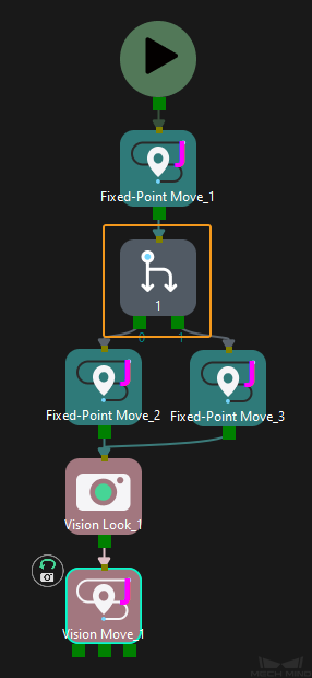
Create a Mech-Viz project. Right-click the project name in the project resource panel in Mech-Viz and select Autoload Project. The Mech-Viz project used for testing should contain a “Branch by Msg” Step that has been renamed to 1 as shown below.
Get Vision Result from Mech-Vision
Set Parameters
-
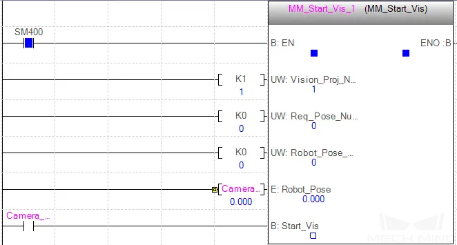
Set the value of Vision_Proj_Num to 1. Then, project No.1 in Mech-Vision will be started.
-
Set the value of Req_Pose_Num to 0. Then, Mech-Vision will return all vision points.
-
Set the value of to 0. Then, the image-capturing pose does not need to be sent to the Mech-Vision project. For example, the image-capturing pose does not need to be sent when the camera is mounted in eye-to-hand mode.
Run the Mech-Vision Project
-
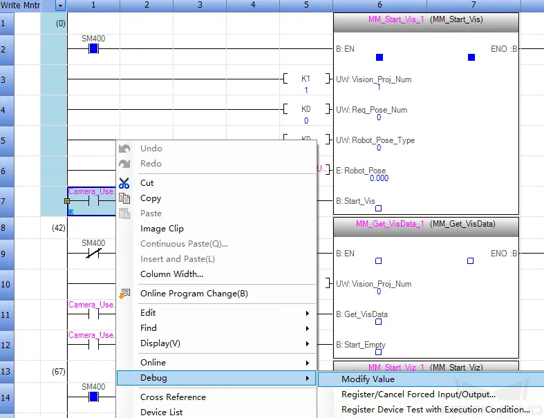
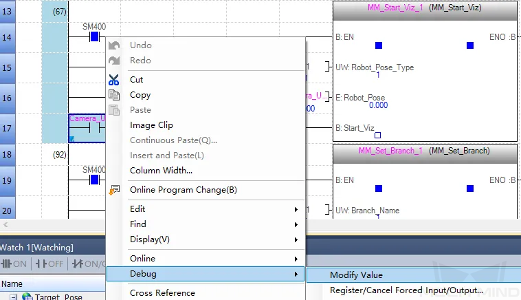
Right-click the input-side Camera_User.Start_Vis of the MM_Start_Vis FB, select , change the value of Camera_User.Start_Vis to 1 to trigger the Mech-Vision project to run, and then change the value of Camera_User.Start_Vis to 0.
-
In the Watch 1 dialog box, if the Mech-Vision project has been successfully triggered, 1102 is displayed for Status_Code.
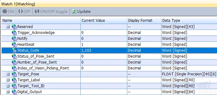
If 10XX is displayed for Status_Code and you want to troubleshoot the issue, see Status Codes and Troubleshooting.
Get Vision Result from Mech-Vision
-
Right-click the input-side Camera_User.Get_VisData of the MM_Get_VisData FB, change the value of Camera_User.Get_VisData to 1 to obtain the vision result, and then change the value of Camera_User.Get_VisData to 0.
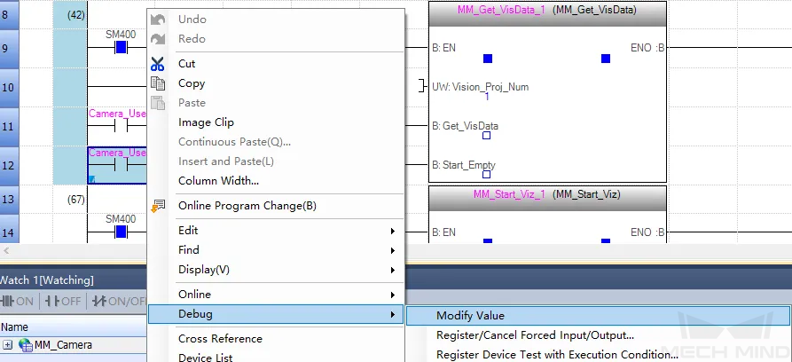
-
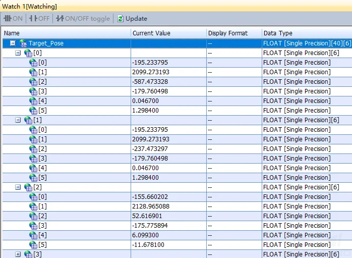
In the Watch 1 dialog box, if the vison result has been successfully obtained, 1100 is displayed for Status_Code.
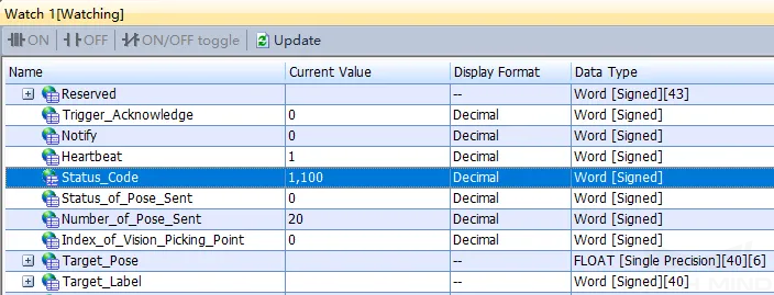
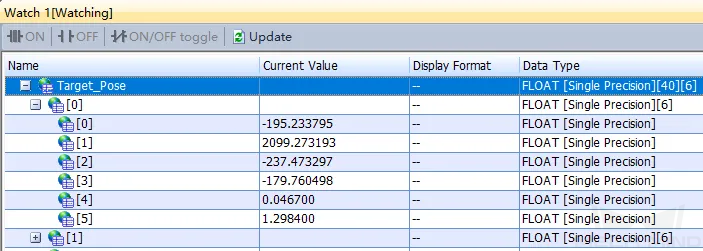
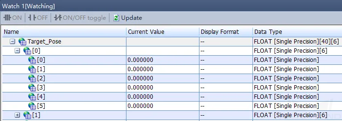
If 10XX is displayed for Status_Code and you want to troubleshoot the issue, see Status Codes and Troubleshooting. Check the values of Target_Pose. The values indicate the pose data of vision points.
Obtain Planned Path from Mech-Viz
Set Parameters
-
Right-click the input-side Camera_User.Start_Empty of the MM_Get_VisData FB, change the value of Camera_User.Start_Empty to 1 to clear the previously obtained vision result, and then change the value of Camera_User.Start_Empty to 0.
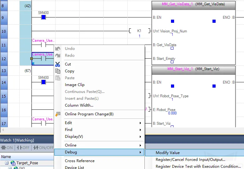
In the Watch 1 dialog box, all values of Target_Pose are 0.
-
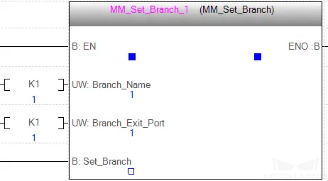
Set the values of Branch_Name and Branch_Exit_Port both to 1 to indicate that the project takes port No.1 of the Branch by Msg No.1 Step of the Mech-Viz project.
-
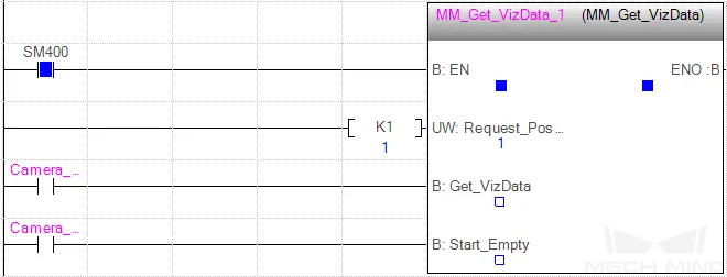
Set the value of Request_Pose_Type to 1 to indicate that the waypoints planned by Mech-Viz will be returned in joint positions.
Run Mech-Viz Project
-
Right-click the input-side Camera_User.Start_Viz of the MM_Start_Viz FB, change the value of Camera_User.Start_Viz to 1 to trigger the Mech-Viz project to run, and then change the value of Camera_User.Start_Viz to 0.
-
In the Watch 1 dialog box, if the Mech-Viz project has been successfully triggered, 2103 is displayed for Status_Code.
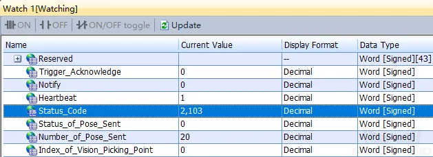
If 20XX is displayed for Status_Code and you want to troubleshoot the issue, see Status Codes and Troubleshooting.
Set the Exit Port for the Branch by Msg Step in Mech-Viz
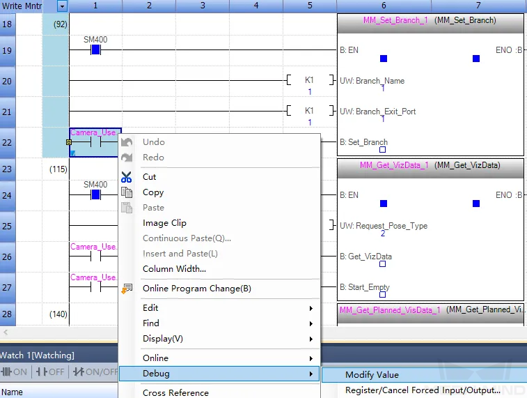
-
Right-click the input-side Camera_User.Set_Branch of the MM_Set_Branch FB, change the value of Camera_User.Set_Branch to 1 to set the exit port of the Branch by Msg Step in the Mech-Viz project, and then change the value of Camera_User.Set_Branch to 0.
-
In the Watch 1 dialog box, if the exit port has been successfully set for the Branch by Msg Step in Mech-Viz, 2105 is displayed for Status_Code.
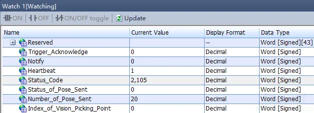
If 20XX is displayed for Status_Code and you want to troubleshoot the issue, see Status Codes and Troubleshooting.
Get Planned Path in Mech-Viz
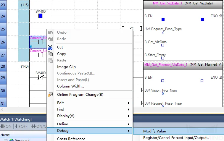
-
Right-click the input-side Camera_User.Get_VizData of the MM_Get_VizData FB, change the value of Camera_User.Get_VizData to 1 to obtain the planned path from Mech-Viz, and then change the value of Camera_User.Get_VizData to 0.
-
In the Watch 1 dialog box, if the planned path has been successfully obtained, 2100 is displayed for Status_Code.
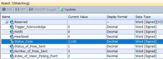
If 20XX is displayed for Status_Code and you want to troubleshoot the issue, see Status Codes and Troubleshooting. Check the values of Target_Pose. The values indicate the pose data of waypoints.