TM Automatic Calibration
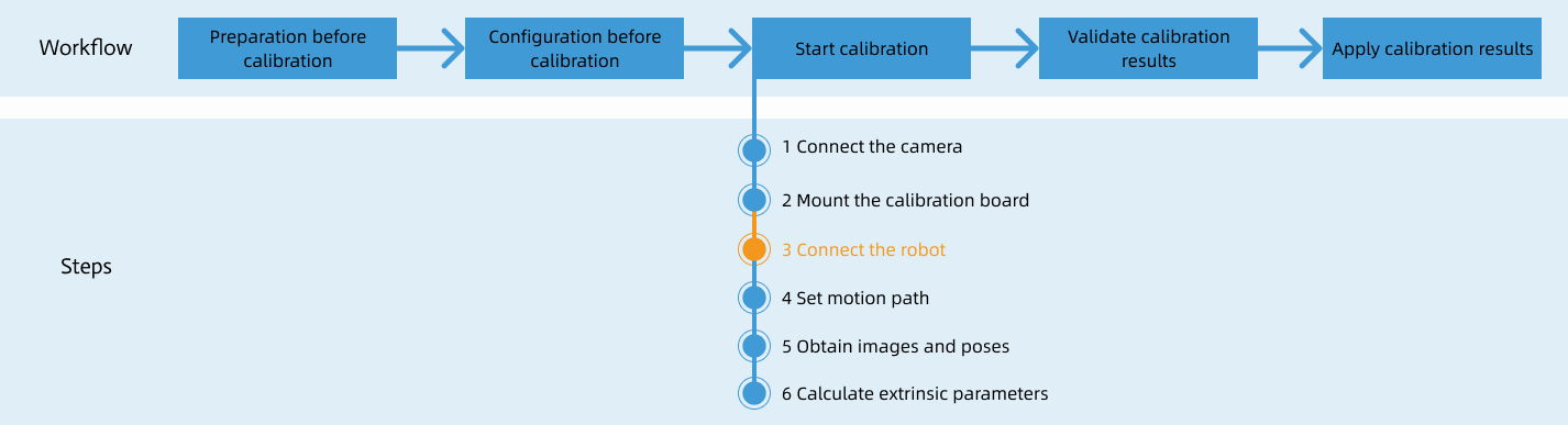
After you set up Standard Interface communication, you can connect the robot to perform automatic calibration. The overall workflow of automatic calibration is shown in the figure below.
Special note
During the calibration procedure, when you reach the Connect the robot step and the Waiting for robot to connect... button appears in Mech-Vision, perform the steps below on the robot side. After you perform the steps, proceed with the remaining steps in Mech-Vision.
|
1. Load the Calibration Program
-
In manual mode (with the Manual light on), open the robot software. Then, click
 and select Project to open the window as shown below.
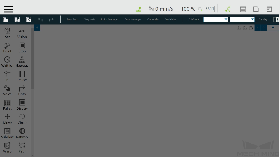
-
Click
 , and select mm_calibaration in the pop-up window, and then click OK.
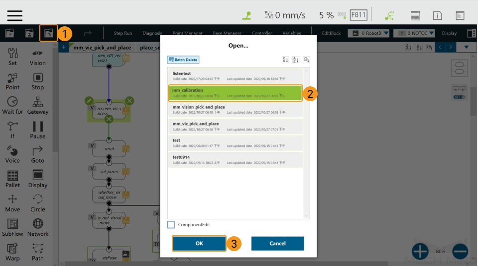
2. Set the Start Point for Calibration
-
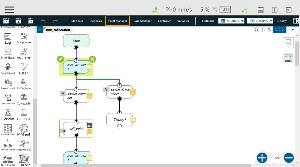
Click Point Manager.
-
Click
 in the pop-up window.
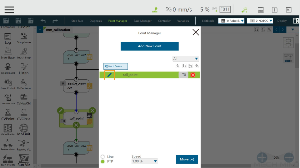
-
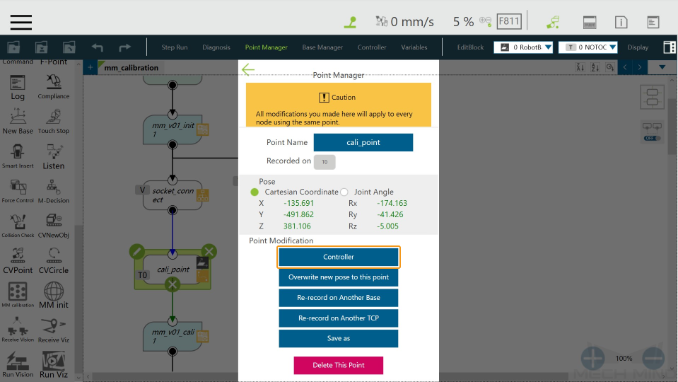
Click Controller.
-
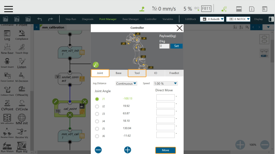
Adjust the robot pose on the Joint or Tool tab, and then click Move. The adjusted robot pose will be used as the start point for calibration.
You can use the position of the robot in the Check the Point Cloud Quality of the Calibration Board step as the calibration start point.
3. Configure the IP Address of the IPC
-
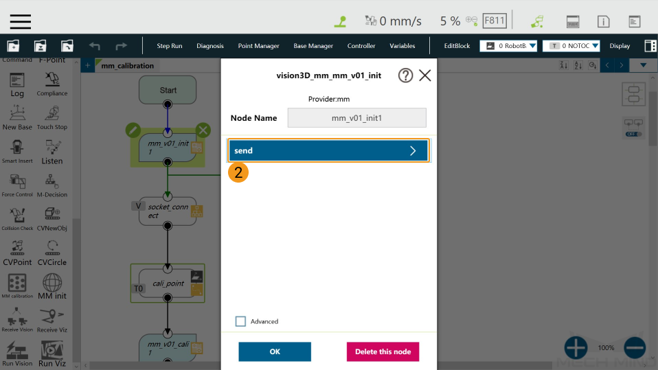
Click the
 icon in the upper-left corner of the mm_v01_init1 node.
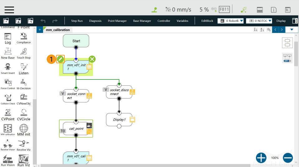
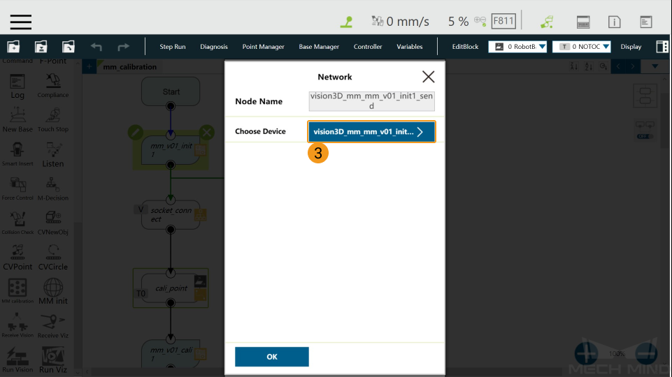
-
Click the icons one by one as shown in the following image.
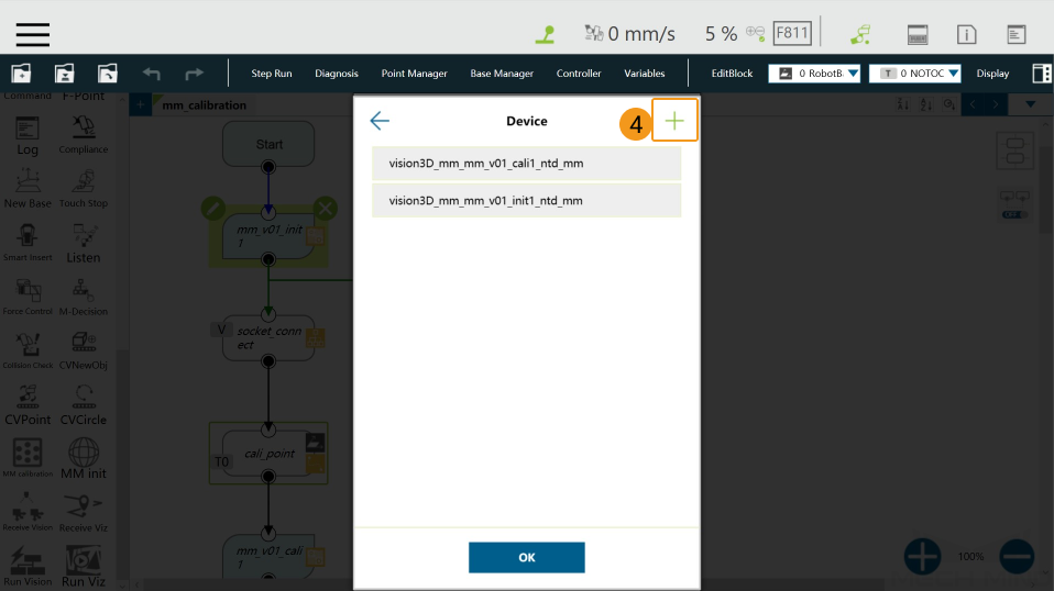
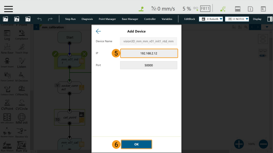
-
Enter the IP address of the IPC in the Add Device window and click OK.
4. Run Calibration Program
-
In the Manual mode (the green Manual light is on), press the
Runbutton on the Robot Stick to run the calibration program.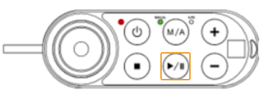
-
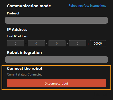
When, in the Configuration window in Mech-Vision, the current status changes to connected and the button Waiting for the robot to connect... changes to Disconnect robot, click Next at the bottom.
-
Perform Step 4 of Start calibration (which is Set motion path) and the subsequent operations based the following links.
-
If the camera mounting mode is eye to hand, see this document and proceed with the relevant operations.
-
If the camera mounting mode is eye in hand, see this document and proceed with the relevant operations.
-