ABB RobotWare 6 Automatic Calibration
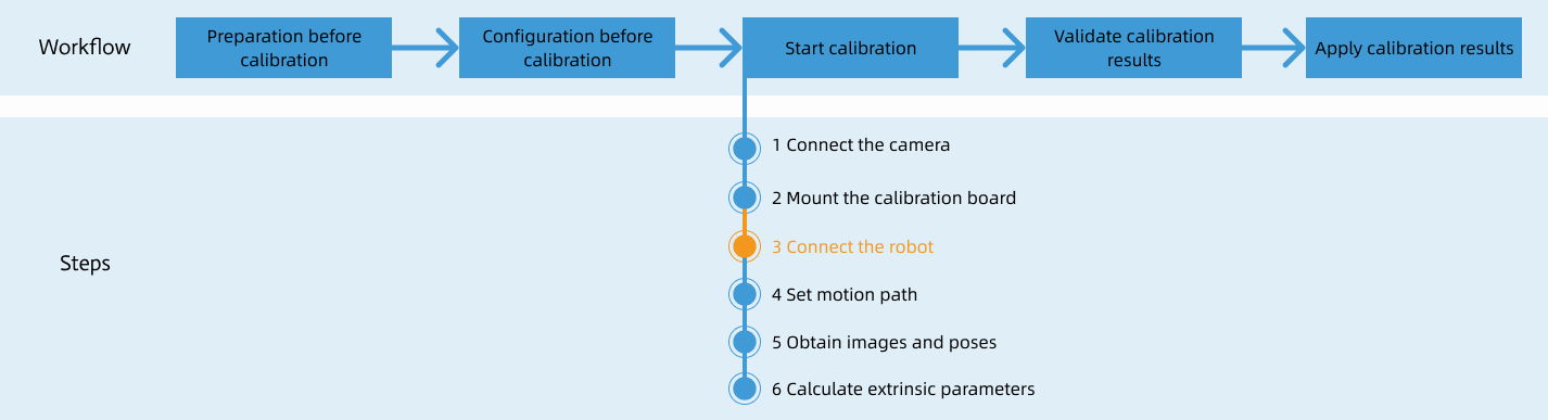
This topic introduces the process of automatic calibration via Standard Interface communication between the ABB RobotWare 6 robot and Mech-Mind Vision System.

Preparation before Calibration

Make preparation before calibration according to the camera mounting method.

Pre-calibration Configuration

  1. Open Mech-Vision, and click the Camera Calibration button in the toolbar. The Configuration before Calibration window will be prompted.

  2. Confirm that the checks are performed, click I’ve finished all checks, and then click Next.

  3. In the Select how to calibrate window, select the New calibration radio button, and then click the Next button.

  4. In the Select calibration task window, select Hand-eye calibration for listed robot from the drop-down list box, click the Select robot model button to select the robot model used by the project, and then click the Next button.

  5. In the Select camera setup window, select the camera mounting method in this project, and then click the Next button.

  6. In the Calibration method and robot control window, select Automatic and Standard Interface, and then click the Calibrate button to go to the Calibration window.

Calibration Procedure

Conduct calibration according to the camera mounting method.

Precautions

  • When you proceed to the third calibration step (connecting the robot) and you click Start interface service button in the Connect the robot window, the button will change to Waiting for the robot to connect.... If the interface service is already started, you do not need to perform this operation.

  • When the button displays Waiting for the robot to connect..., perform the following steps on the robot side. Then, continue the calibration in the software.

1. Select and Modify Calibration Program
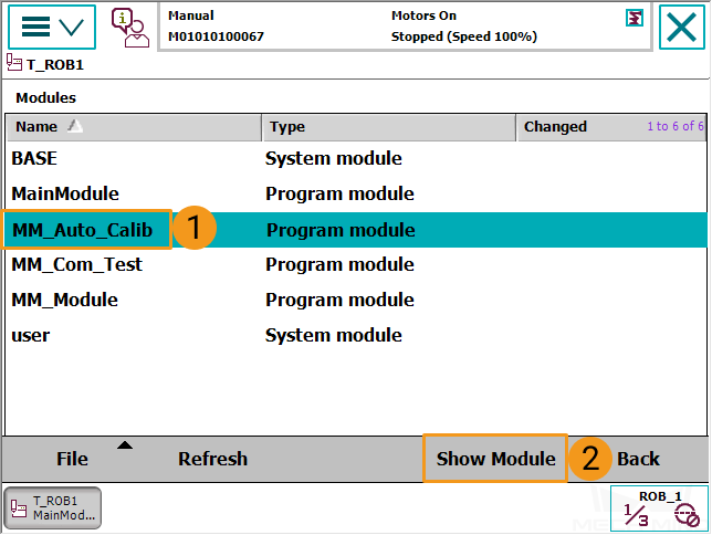
In the manual mode, select Program Editor  Tasks and Programs  T_ROB1  Show Module, and locate and open the program module MM_Auto_Calib in T_ROB1. Ensure that the IP address of the MM_Init_Socket line in the program module is the IP address of the IPC, and the port is the same as the setting in Mech-Vision. For detailed instructions on the operation, refer to select and modify the communication test program.

calilbration process1
calilbration process2

2. Teach Calibration Start Point

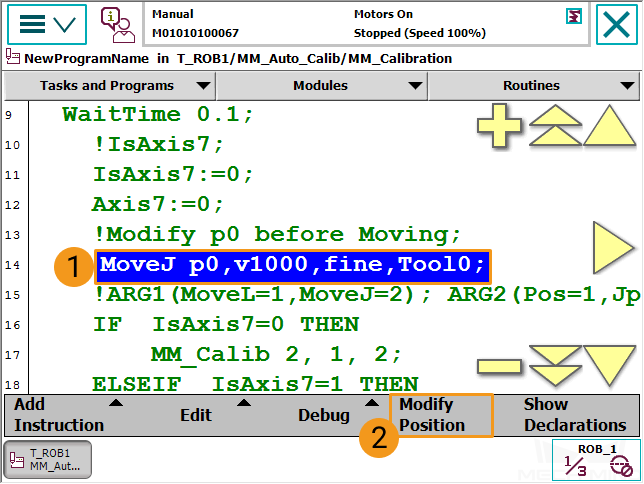
  1. Move the robot to the start point for calibration.

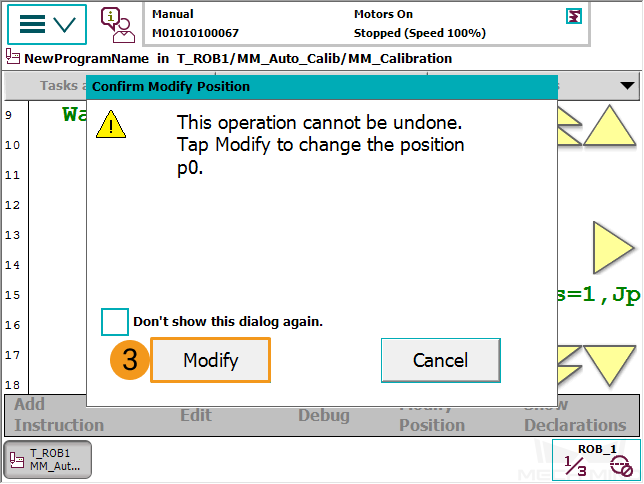
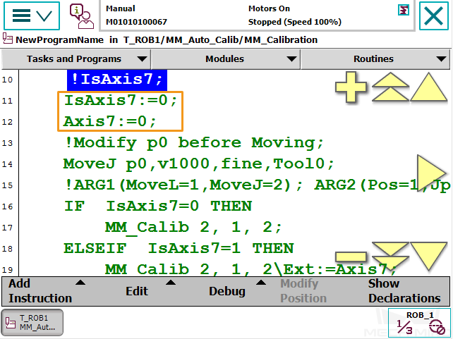
  2. Select the line in the image below and then select Modify Position. Select Modify in the dialogue box to save the robot’s current pose to P0.

    calilbration process3
    calilbration process4
  3. If there is a 7th axis which is controlled by the robot on site, modify “IsAxis7 :=0;” to “IsAxis7 :=1;” and modify the value of Axis7 accordingly (Axis7 = XX, XX refers to the current value of the 7th axis). If there is not a 7th axis, or the 7th axis is controlled by a PLC, you may skip this step.

    calilbration process5

3. Run Calibration Program
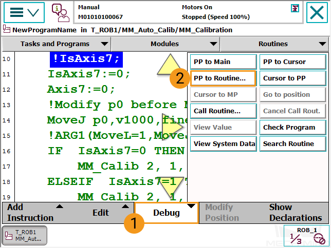
  1. In the manual mode, select Debug  PP to Routine... in the interface of the program MM_Auto_Calib.

    calilbration process6
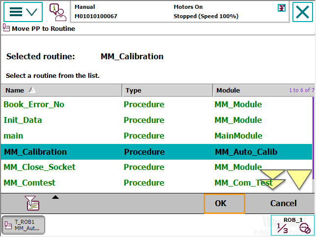
  2. After selecting MM_Calibration, select OK.
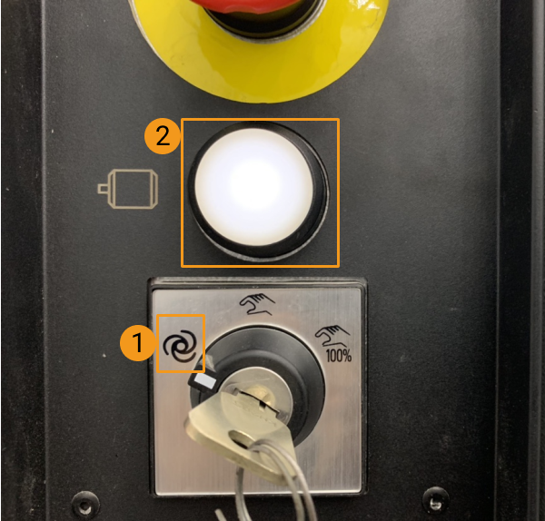
    calilbration process7
  3. Switch the key in the controller to the automatic mode, and ensure that the motor indicator light is on.

    calilbration process8

    If the Auto Condition Reset warning (which resets the program pointer to the main program) appears in the teach pendant interface, the program cannot run normally in the subsequent steps.

    calilbration process11

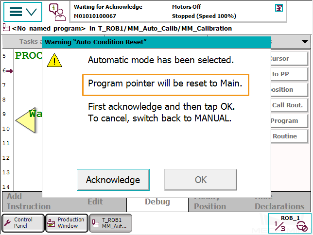
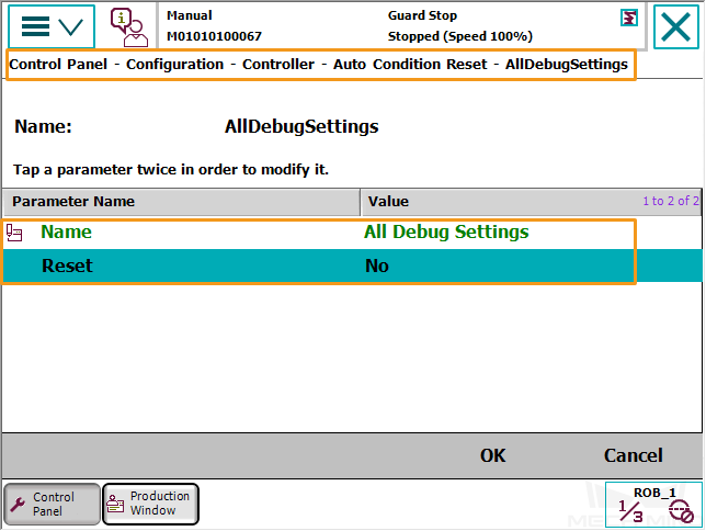
    In this case, you can switch to the manual mode, select the menu in the upper-left corner  Control Panel  Configuration  Topics  Controller  Auto Condition Reset  AllDebugSettings, set Reset to No, and then try again.

    calilbration process12
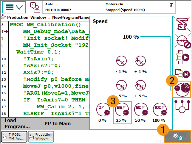
  4. Follow the steps in the image to modify the speed to 25%.
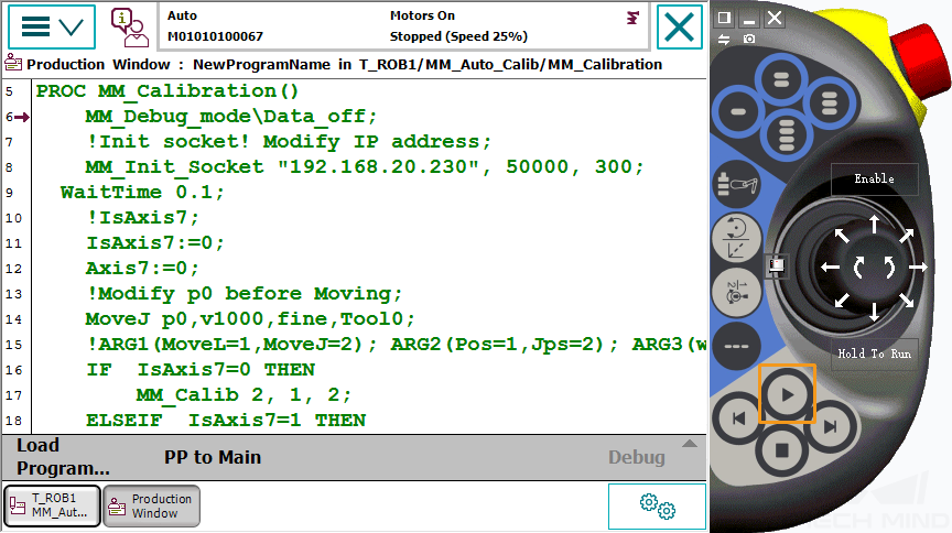
    calilbration process9
  5. Press the start key when the interface displays the content below. 
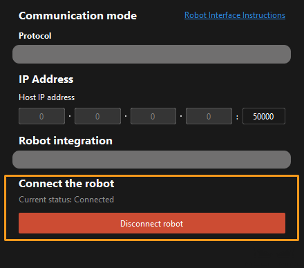
When, in the Configuration window in Mech-Vision, the current status changes to connected and the button Waiting for the robot to connect changes to Disconnect, click Next. Next, proceed to the fourth step of the calibration process (i.e. setting the movement path).

    calilbration process10
    start calilbration1

Change the Extrinsic Parameter File

If the camera’s extrinsic parameter file has been used by a Mech-Vision project, you need to change the extrinsic parameter file used by the Mech-Vision project to a new one after you finish the hand-eye calibration.

  1. Select the Capture Images from Camera Step.

    change calibration parameter group
  2. In the Step Parameters panel, click change calibration parameter group icon of the Calibration Parameter Group parameter, and select the newly calibrated extrinsic parameter file.

Calibration-Related Status Codes

During automatic calibration via Standard Interface communication, the vision system returns data together with the status code to the robot. Status codes, which are categorized into error codes and normal status codes, indicate the command execution status. Calibration related status codes are listed in the tables below.

Error codes

Error code Description

Calibration: Parameter error

Calibration: No calibration flange pose provided from Mech-Vision

Calibration: No calibration joint angles provided from Mech-Vision

Calibration: Robot failed to reach calibration point

Normal status codes

Normal status code Description

7100

Calibration: Robot moved to the calibration point successfully

7101

Calibration: Pose received from Mech-Vision successfully

We Value Your Privacy

We use cookies to provide you with the best possible experience on our website. By continuing to use the site, you acknowledge that you agree to the use of cookies. If you decline, a single cookie will be used to ensure you're not tracked or remembered when you visit this website.