Example Program 11: MM_S11_Viz_Timer
Program Introduction
Description |
The robot uses a timer to calculate the time taken from establishing the communication to completing picking and placing each time. |
||
File path |
You can navigate to the installation directory of Mech-Vision and Mech-Viz and find the file by using the
|
||
Project |
Mech-Vision and Mech-Viz projects |
||
Prerequisites |
|
| This example program is provided for reference only. Before using the program, please modify the program according to the actual scenario. |
Program Description
This part describes the MM_S11_Viz_Timer example program.
| The only difference between the MM_S11_Viz_Timer example program and the MM_S2_Viz_Basic example program is that MM_S11_Viz_Timer can use a timer to calculate the required time (this code of this feature is bolded). As such, only the feature of using a timer to calculate the required time is described in the following section. For information about the parts of MM_S11_Viz_Timer that are consistent with those of MM_S2_Viz_Basic, see Example Program 2: MM_S2_Viz_Basic. |
MODULE MM_S11_Viz_Timer
!----------------------------------------------------------
! FUNCTION: trigger Mech-Viz project and get planned path,
! add a timer to record cycle time
! Mech-Mind, 2023-12-25
!----------------------------------------------------------
!define local num variables
LOCAL VAR num pose_num:=0;
LOCAL VAR num status:=0;
LOCAL VAR num toolid{5}:=[0,0,0,0,0];
LOCAL VAR num vis_pose_num:=0;
LOCAL VAR num count:=0;
LOCAL VAR num label{5}:=[0,0,0,0,0];
LOCAL VAR clock timer;
LOCAL VAR num timer_val;
!define local joint&pose variables
LOCAL CONST jointtarget home:=[[0,0,0,0,90,0],[9E+9,9E+9,9E+9,9E+9,9E+9,9E+9]];
LOCAL CONST jointtarget snap_jps:=[[0,0,0,0,90,0],[9E+9,9E+9,9E+9,9E+9,9E+9,9E+9]];
LOCAL PERS robtarget camera_capture:=[[302.00,0.00,558.00],[0,0,-1,0],[0,0,0,0],[9E+9,9E+9,9E+9,9E+9,9E+9,9E+9]];
LOCAL PERS robtarget drop_waypoint:=[[302.00,0.00,558.00],[0,0,-1,0],[0,0,0,0],[9E+9,9E+9,9E+9,9E+9,9E+9,9E+9]];
LOCAL PERS robtarget drop:=[[302.00,0.00,558.00],[0,0,-1,0],[0,0,0,0],[9E+9,9E+9,9E+9,9E+9,9E+9,9E+9]];
LOCAL PERS jointtarget jps{5}:=
[
    [[11.1329,49.0771,-36.9666,0.5343,79.2476,-169.477],[9E+9,9E+9,9E+9,9E+9,9E+9,9E+9]],
    [[11.2355,52.1281,-23.3996,0.5938,62.6295,-169.548],[9E+9,9E+9,9E+9,9E+9,9E+9,9E+9]],
    [[11.1329,49.0771,-36.9666,0.5343,79.2476,-169.477],[9E+9,9E+9,9E+9,9E+9,9E+9,9E+9]],
    [[11.1329,49.0771,-36.9666,0.5343,79.2476,-169.477],[9E+9,9E+9,9E+9,9E+9,9E+9,9E+9]],
    [[0,0,0,0,90,0],[9E+9,9E+9,9E+9,9E+9,9E+9,9E+9]]
];
!define local tooldata variables
LOCAL PERS tooldata gripper1:=[TRUE,[[0,0,0],[1,0,0,0]],[0.001,[0,0,0.001],[1,0,0,0],0,0,0]];

PROC Sample_11()
    !set the acceleration parameters
    AccSet 50, 50;
    !set the velocity parameters
    VelSet 50, 1000;
    !move to robot home position
    MoveAbsJ home\NoEOffs,v3000,fine,gripper1;
    !initialize communication parameters (initialization is required only once)
    MM_Init_Socket "127.0.0.1",50000,300;
LOOP:
    !reset timer to 0
    ClkReset timer;
    !start timer
    ClkStart timer;
    !move to image-capturing position
    MoveL camera_capture,v1000,fine,gripper1;
    !open socket connection
    MM_Open_Socket;
    !trigger Mech-Viz project
    MM_Start_Viz 2,snap_jps;
    !get planned path, 1st argument (1) means getting pose in JPs
    MM_Get_VizData 1, pose_num, vis_pose_num, status;
    !check whether planned path has been got from Mech-Viz successfully
    IF status <> 2100 THEN
        !add error handling logic here according to different error codes
        !e.g.: status=2038 means no point cloud in ROI
        Stop;
    ENDIF
    !close socket connection
    MM_Close_Socket;
    !save waypoints of the planned path to local variables one by one
    MM_Get_Jps 1,jps{1},label{1},toolid{1};
    MM_Get_JPS 2,jps{2},label{2},toolid{2};
    MM_Get_JPS 3,jps{3},label{3},toolid{3};
    !follow the planned path to pick
    !move to approach waypoint of picking
    MoveAbsJ jps{1},v1000,fine,gripper1;
    !move to picking waypoint
    MoveAbsJ jps{2},v300,fine,gripper1;
    !add object grasping logic here, such as "setdo DO_1, 1;"
    Stop;
    !move to departure waypoint of picking
    MoveAbsJ jps{3},v1000,fine,gripper1;
    !move to intermediate waypoint of placing
    MoveJ drop_waypoint,v1000,z50,gripper1;
    !move to approach waypoint of placing
    MoveL RelTool(drop,0,0,-100),v1000,fine,gripper1;
    !move to placing waypoint
    MoveL drop,v300,fine,gripper1;
    !add object releasing logic here, such as "setdo DO_1, 0;"
    Stop;
    !move to departure waypoint of placing
    MoveL RelTool(drop,0,0,-100),v1000,fine,gripper1;
    !move back to robot home position
    MoveAbsJ home\NoEOffs,v3000,fine,gripper1;
    !stop timer
    ClkStop timer;
    !read timer value and display the cycle time in log message on teach pendant
    timer_val:=ClkRead(timer);
    TPWrite "single cycle time: "numtostr(timer_val,3)"s.";
    GOTO LOOP;
ENDPROC
ENDMODULE
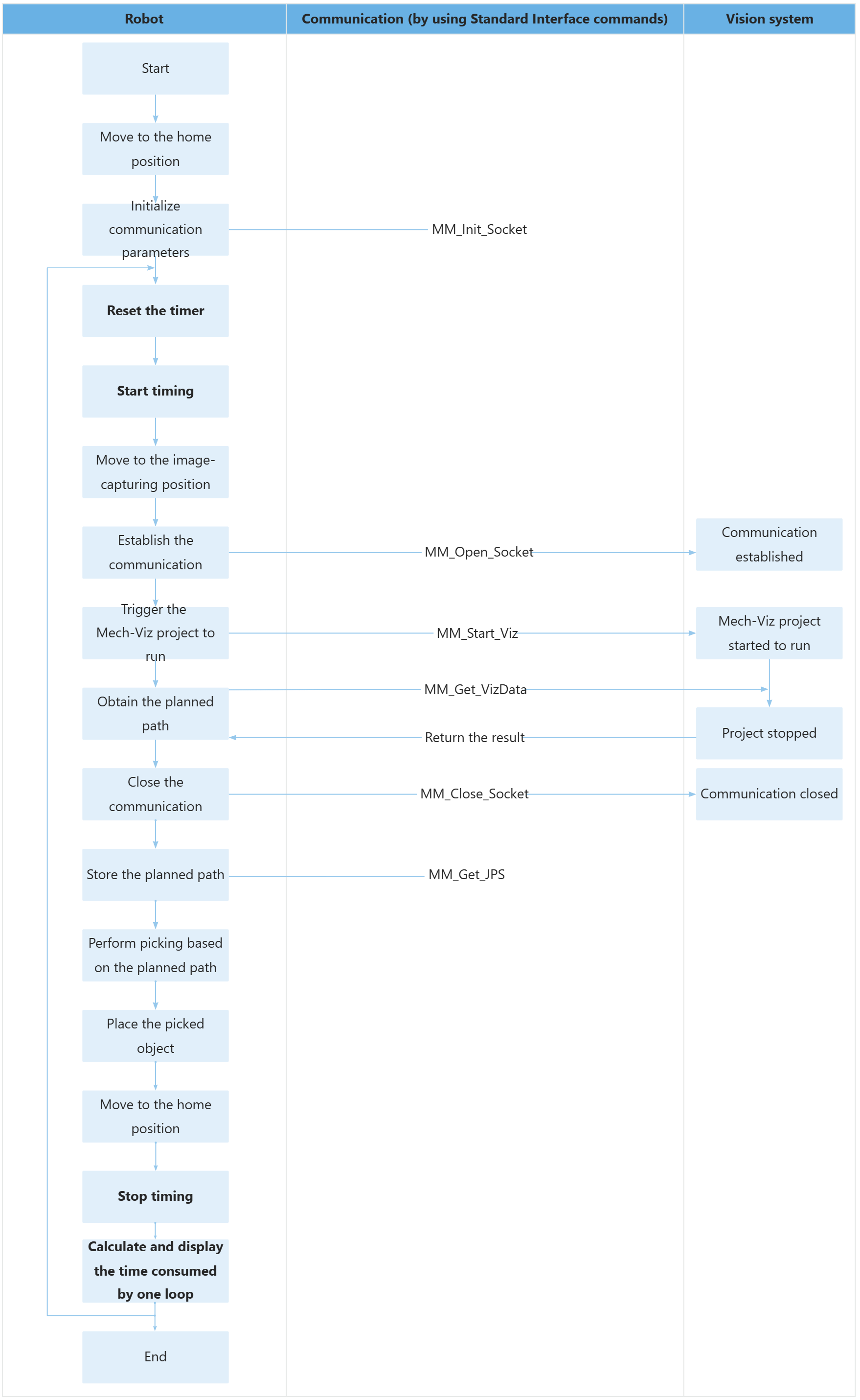
The workflow corresponding to the above example program code is shown in the figure below.

The table below describes the feature of using a timer to calculate the required time.
| Feature | Code and description |
|---|---|
Calculate the time taken from establishing the communication to completing picking and placing each time by looping |
The above code indicates that the program loops through the code between LOOP and GOTO LOOP. The above code resets the timer to 0. The above code starts running the timer. The above code stops the timer. In the above example, the ClkRead command reads the time calculated by the timer (i.e., the amount of time taken from establishing the communication to completing picking and placing each time) and then assigns the time value to the timer_val variable.
The entire statement displays the calculated time on the teach pendant screen. |