Hand-Eye Automatic Calibration with the CRX Plugin
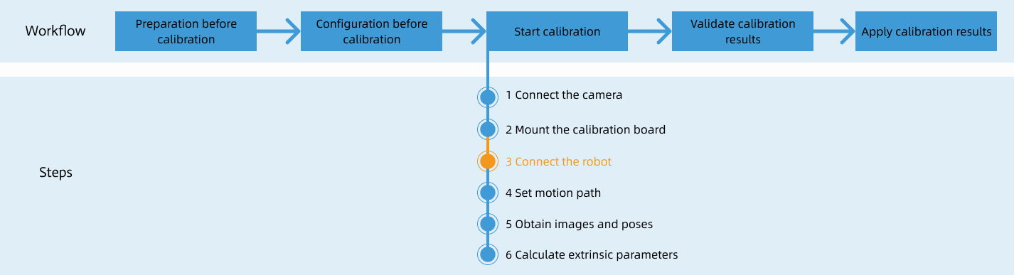
After you set up Standard Interface communication, you can connect the robot to perform automatic calibration. The overall workflow of automatic calibration is shown in the figure below.
Special note
During the calibration procedure, when you reach the Connect the robot step and the Waiting for robot to connect... button appears in Mech-Vision, perform the steps below on the robot side. After you perform the steps, proceed with the remaining steps in Mech-Vision.
|
1. Create a Calibration Program
-
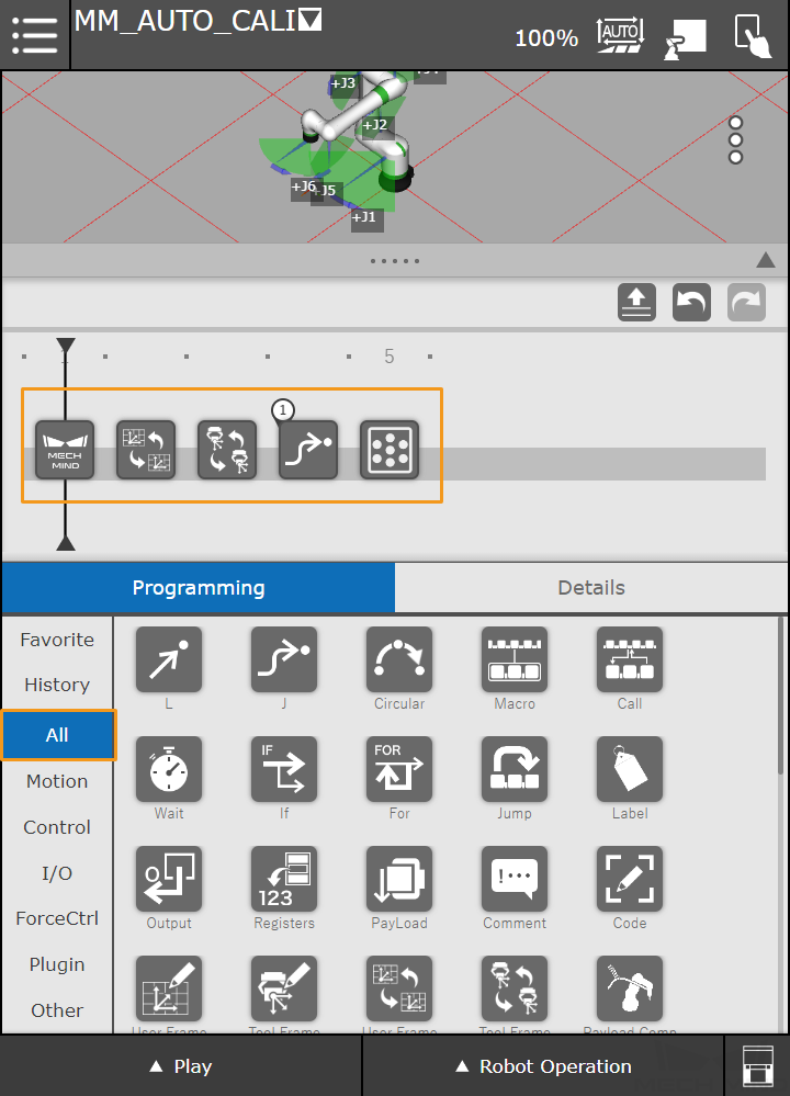
Create a new robot program. The program name in this example is MM_AUTO_CALI. Select Programming, and drag the commands in the ALL tab to the program line in the following order: Mech-System SocketInit → User Frame Select → Tool Frame Select → J → Mech-Eye Calibration.
-
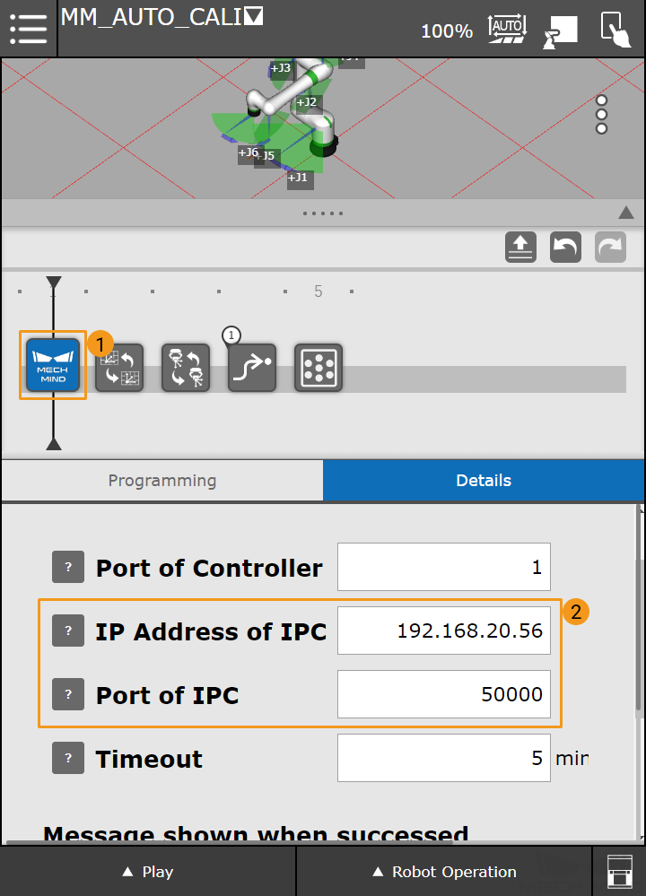
Press Mech-System SocketInit on the program line to view the details of the command. Set the IP Address of IPC to the host address and set the Port of IPC to the port number configured in Mech-Vision.
-
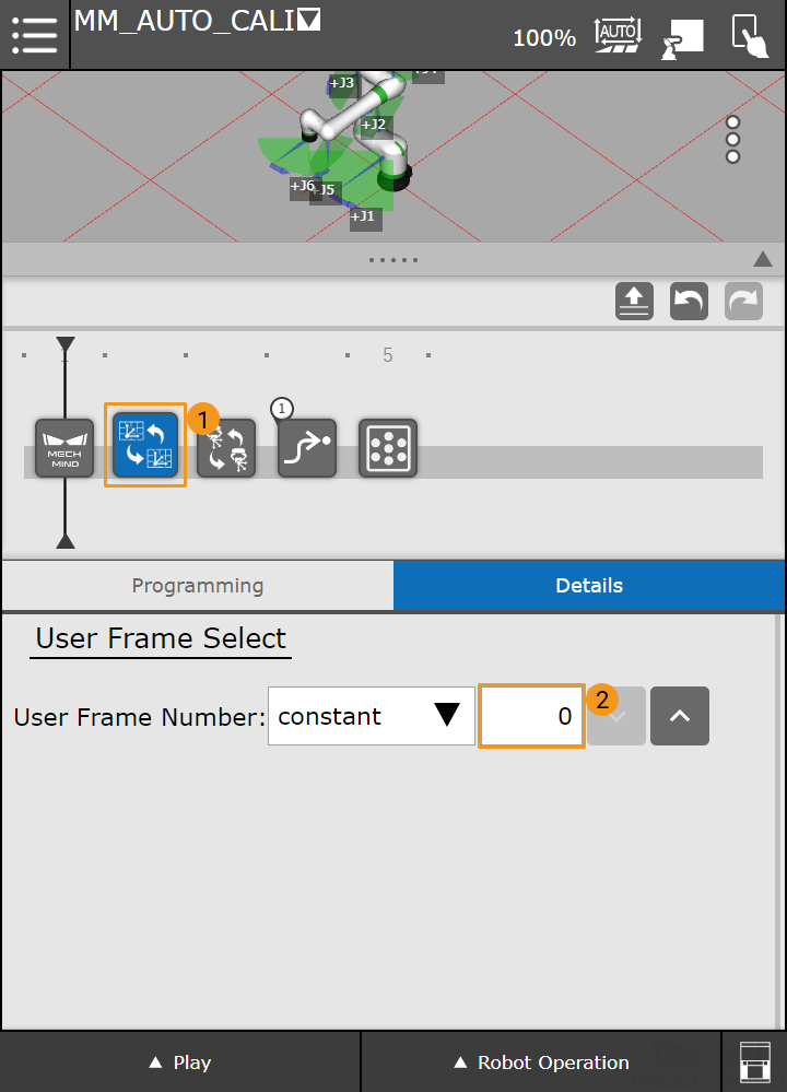
Press User Frame Select, and set the User Frame Number to 0.
-
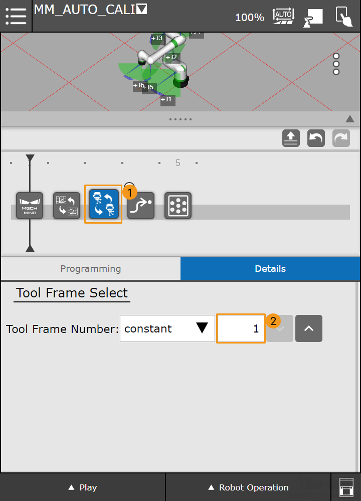
Press Tool Frame Select, and set the Tool Frame Number to 1.
2. Teach Calibration Start Point
-
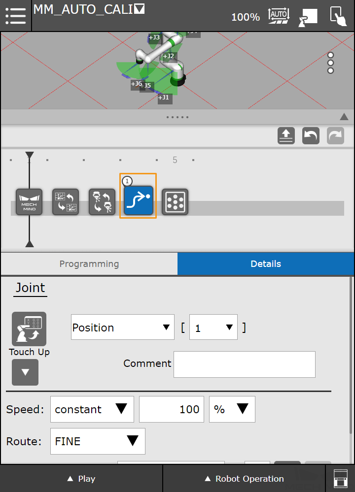
Press J motion.
-
Manually move the robot to the calibration start point.
You can use the position of the robot in the Check the Point Cloud Quality of the Calibration Board step as the calibration start point.
-
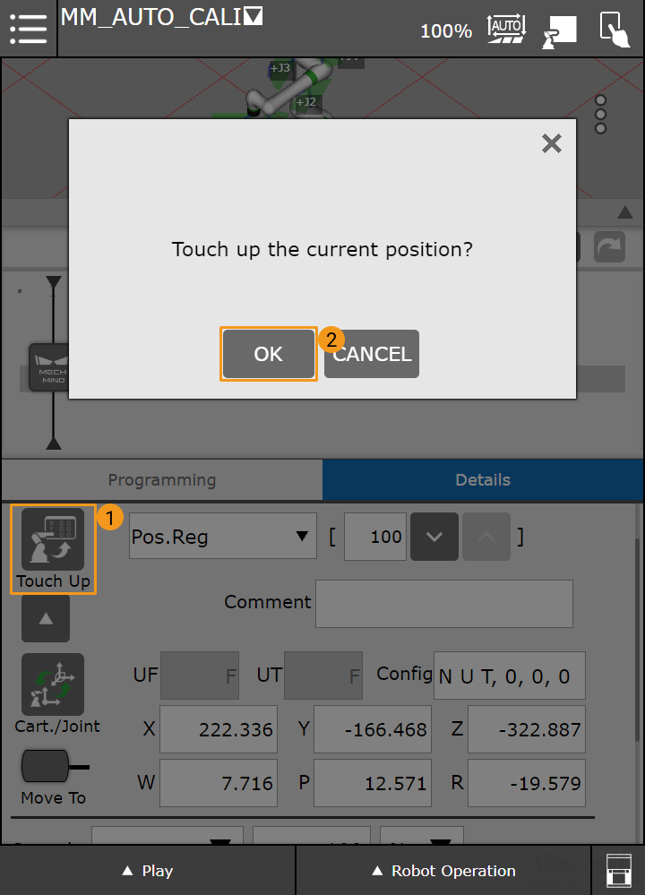
Select Pos.Reg, and enter the number of the pose register. The register 100 is used in this example. Then press the
 icon to display the Cart./Joint button.
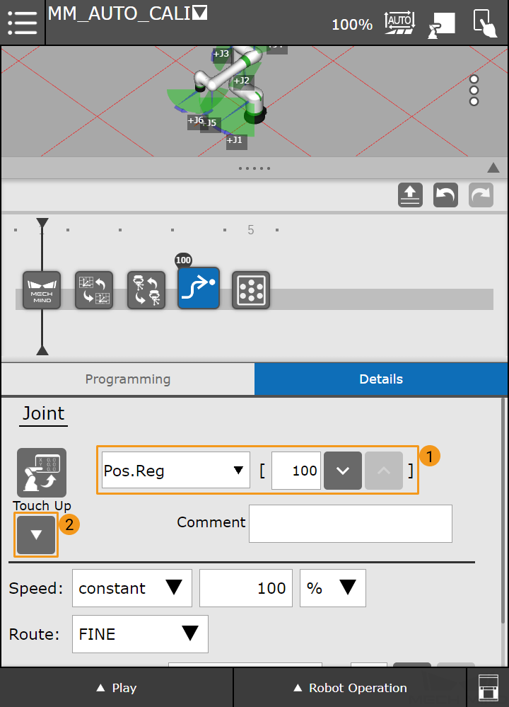
-
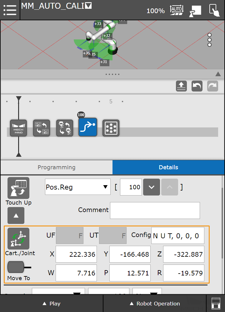
Press Cart./Joint to switch to Cartesian reference frame.
-
Press the Touch Up button, and select OK in the dialog box to save the start point of calibration.
-
-
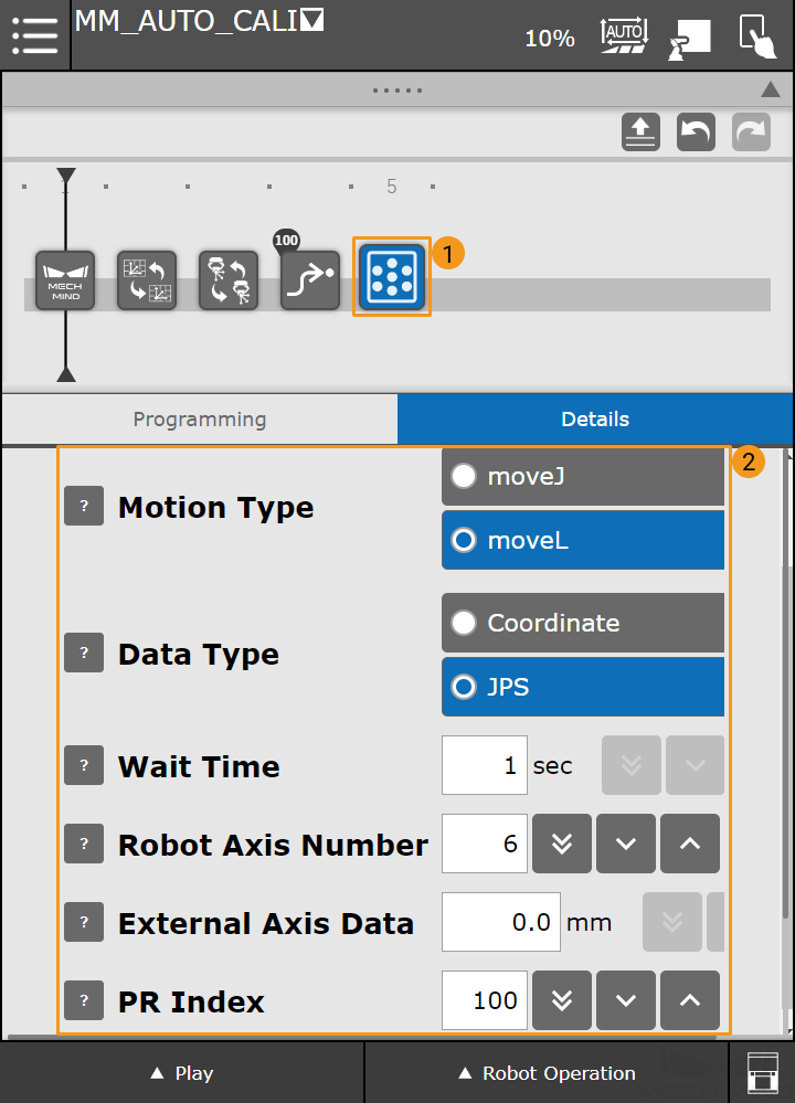
Press Mech-Eye Calibration, and configure the parameters as shown in the figure below.
-
Motion Type: Specify the motion type during the automatic calibration process.
-
Data Type: The pose type the robot sends.
-
Wait Time: The time the robot waits to avoid shaking after it moves to the calibration point.
-
PR Index: Set the register number where the calibration start point is stored.
-
3. Run Calibration Program
-
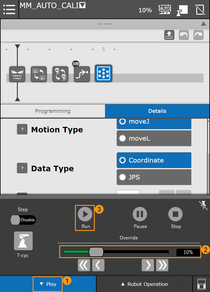
Switch to the Automatic mode, and press Play in the lower left corner. Reduce the velocity, and then press Run.
-
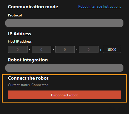
When, in the Configuration window in Mech-Vision, the current status changes to connected and the button Waiting for the robot to connect... changes to Disconnect robot, click Next at the bottom.
-
Perform Step 4 of Start calibration (which is Set motion path) and the subsequent operations based the following links.
-
If the camera mounting mode is eye to hand, see this document and proceed with the relevant operations.
-
If the camera mounting mode is eye in hand, see this document and proceed with the relevant operations.
-