KUKA Automatic Calibration
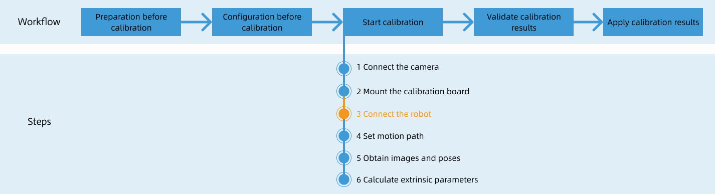
After you set up Standard Interface communication, you can connect the robot to perform automatic calibration. The overall workflow of automatic calibration is shown in the figure below.
Special note
During the calibration procedure, when you reach the Connect the robot step and the Waiting for robot to connect... button appears in Mech-Vision, perform the steps below on the robot side. After you perform the steps, proceed with the remaining steps in Mech-Vision.
|
1. Select the Calibration Program
-
Switch to the Administrator mode following the instruction on switching to the Expert mode.
-
On the teach pendant, open the
KRC:\R1\mmfolder, select mm_module.src, and then press Select.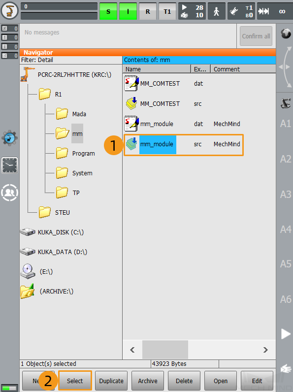
2. Teach Calibration Start Point
-
Move the robot to the start point for calibration.
You can use the position of the robot in the Check the Point Cloud Quality of the Calibration Board step as the calibration start point.
-
Select the line containing “PTP P0 Vel=100 % PDAT0 Tool[1]:Tool1 Base[0]” and move the cursor to this line. Select Block selection. When the cursor appears in the front of the line, select Touch-Up.
If the Touch-Up button does not work and an error occurs, try deleting the current motion command and then recreate the motion command. 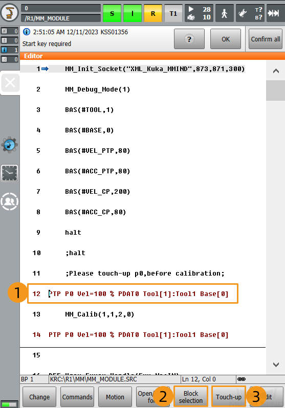
-
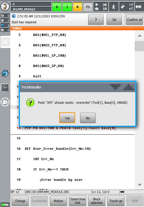
Press Yes in the pop-up window to finish teaching the start point for calibration.
3. Run Calibration Program
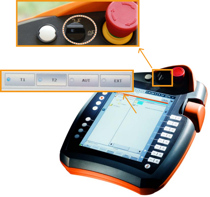
Before you start, we recommend that you see the following instructions to learn how to switch between running modes.
Turn the key switch to horizontal. Select the running mode, for example, T1 or AUT, in the pop-up dialog box on the screen. Then, turn the switch back to vertical.
| T1 stands for the Manual Reduced Velocity mode, and AUT stands for the Automatic mode. |
-
Switch to the T1 mode following the instructions above.
-
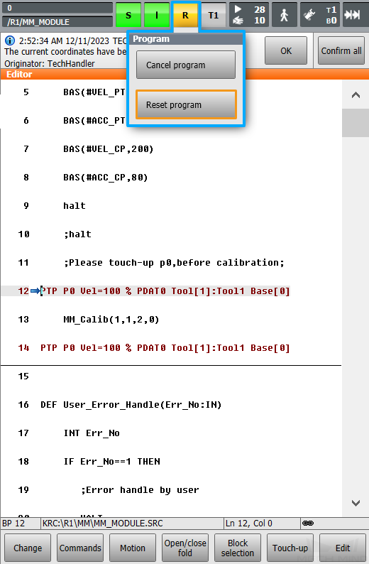
Select R on the teach pendant. Select Reset program in the pop-up window.
-
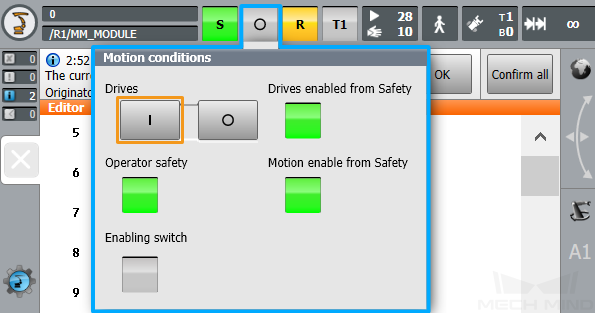
Select O. Then, select I in the pop-up window to switch the status of Drives to I. Skip this step if the status of Drives is I in the first place.
-
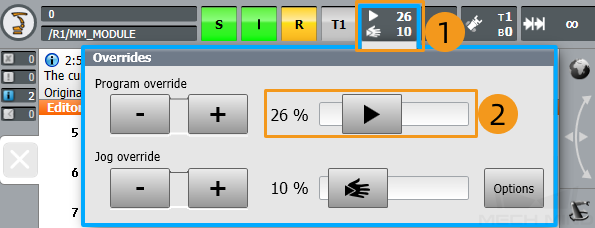
Adjust the value of Program override to a proper speed. Watch the robot’s motion when the program is running.
-
Switch to the AUT mode following the instructions above.
-
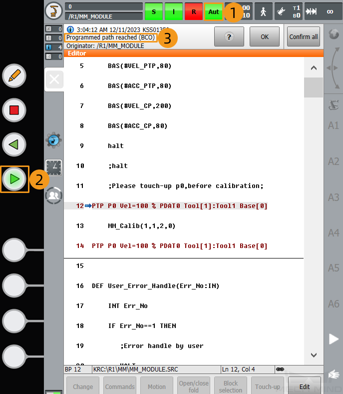
Press and hold the green run button on the front of the teach pendant until the arrow moves to the line “PTP P0 Vel=100 % PDAT0 Tool[1]:Tool1 Base[0]”, which stands for the calibration start point. The message “Programmed path reached (BCO)” will prompt on the top of the screen.
-
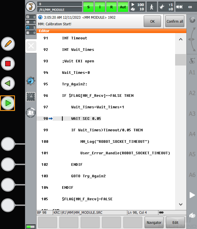
Then, press the run button to continue to execute the program. (The R button turns green when the program is running.)
-
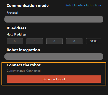
When, in the Configuration window in Mech-Vision, the current status changes to connected and the button Waiting for the robot to connect... changes to Disconnect robot, click Next at the bottom.
-
Perform Step 4 of Start calibration (which is Set motion path) and the subsequent operations based the following links.
-
If the camera mounting mode is eye to hand, see this document and proceed with the relevant operations.
-
If the camera mounting mode is eye in hand, see this document and proceed with the relevant operations.
-