Fundamentals
Solution and Project
Solution is a collection of configurations and data of robot communication, vision processing, path planning and other functions, which are all integral components of a vision application.
Based on the image data captured on-site, a Mech-Vision project performs a series of vision processing and outputs the vision results.
Mech-Viz projects refer to the robot path planning projects created in Mech-Viz. It can use the vision result from Mech-Vision to dynamically generate collision-free paths of robot motion.
Mech-Vision projects combine with the Mech-Viz projects to form solutions for 3D robot guidance. A solution can contain several Mech-Vision projects, but at most one Mech-Viz project.
Starting from Mech-Viz 2.0.0, the Mech-Viz project must belong to a solution and cannot be used separately. Please refer to Project and Solution to learn more about their operations.
| “Projects” mentioned in Mech-Viz’s user manual refer to Mech-Viz projects unless there are special instructions. |
Project Resources
Project resources refer to various fundamental resources used in the project, including the robot, tools, target objects, and scene objects.
Robot |
In Mech-Viz, robots refer to multi-joint robotic arms or the gantry robot for industrial use. |
Tools |
Tools, such as grippers and suction cups, are specially designed mechanical devices attached to the flange of the robot to perform various tasks. |
Target Objects |
Target objects refer to the objects on which the tool performs tasks, such as cartons, metal parts, parts to be glued or welded, etc. |
Scene Objects |
Scene objects, usually including the safety fence, picking bin, tray, camera, camera mounting frame, and so on, refer to objects in the real scenarios where the robot performs various tasks. |
Pose
TCP (Tool Center Point)
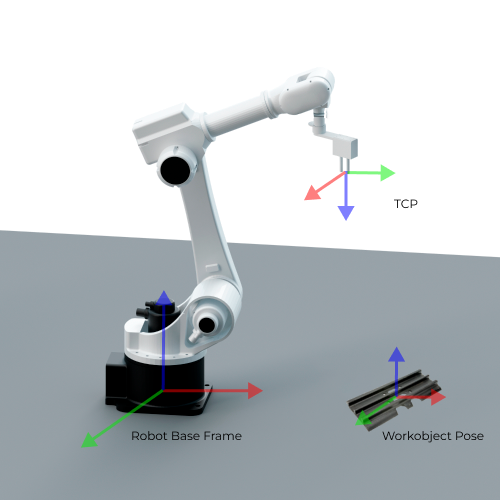
TCP is the pose of a specific point on the tool or outside the tool relative to the flange at the robot end.
In order to complete tasks such as picking, we usually say that the robot should move to a specific point in space, which actually means its TCP should move to that point.
Target Object Pose
The target object pose is the pose of a certain point on the target object relative to the robot base frame. When placing the target object, we usually make the its pose coincide with a certain target pose.
(Target Object) Pick Point
There may be several different pick points on one target object, which are output by Mech-Vision. When picking the target object, the robot will move its TCP to the location of the pick point so that the origins and X-axes of these two points coincide with each other, while the directions of their Y-axes and Z-axes are opposite.
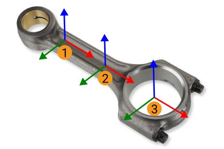
Among them, ① and ② are the pick points of shafts, while ③ is the pick point of ring center.
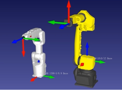
Robot Pose
The robot pose usually refers to the position and orientation of the robot in the 3D space. It is expressed in the way of tool pose or joint positions.
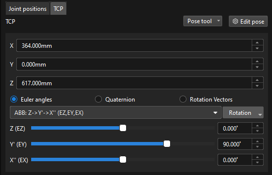
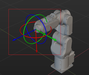
Tool Pose
The tool pose refers to the pose of the tool frame relative to the robot frame.
The tool pose determines the position (x, y, z) and orientation (usually represented by Euler angles, rotation matrix, and quaternions) of the tool. It focuses on the positional relationship between the tool and the working space and describes the position and orientation of the tool, such as robotic claw, and welding torch, when the robot performs a task.
-
Euler Angles
Euler Angels are used to describe the rotation of the object in the 3D space.
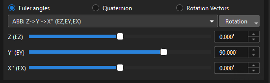
The Euler angles consist of three angles that correspond to the rotation of each of the three axes. These three axes usually rotate around the X, Y and Z-axis of the object’s fixed reference frame respectively. The same orientation can be expressed in different ways using multiple Euler angles. To avoid ambiguity, a consistent definition of Euler angles is applied in the robots from different brands. For more information on Euler angle conventions and representations, please refer to Euler Angles.


-
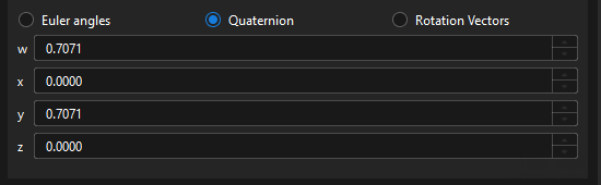
Quaternions
To avoid the gimbal lock problem of using Euler angles, some robot manufacturers use quaternions to represent the orientations in the space. A quaternion roughly refers to using three numbers to define the spatial rotation axis and using the fourth number to define the rotation angle. The tool reference frame can reach the target pose from its initial state by rotating the angle around the spatial rotation axis.
-
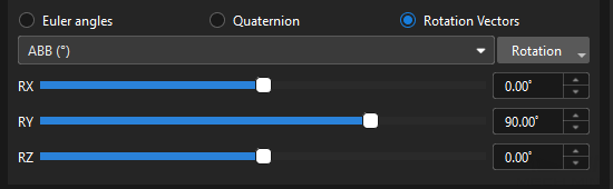
Rotation Vector
The rotation vector, also known as the axial angle, is used to describe the rotation state of the tool.
Currently, it is only used by UR robots.
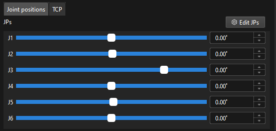
Joint Positions
Joint positions refer to the rotation angles of each joint of the robot relative to its initial position or reference position. This description can represent the state of each joint in line with the hardware structure of the robot.
The joint positions are mapped to the tool pose by forward kinematics computation, while the tool pose is mapped to the joint positions by inverse kinematic computation.
Flange Pose
The flange pose is the pose of the robot flange frame relative to the robot reference frame, whose representation is the same as that of the tool pose. It can be seen as a special tool pose that the TCP is at the center of the flange without any rotation.
The default orientation of the flange reference frame defined by each robot manufacturer is different, resulting in different default angles for the flange pose. For example, the default X-axis orientation for ABB robots is downward, while that for FANUC robots is upward. In addition, most robots have a flange pose with the Z-axis perpendicular to the flange surface facing outward, but for the TURIN robots, it is the X-axis that is perpendicular to the flange surface facing outward.
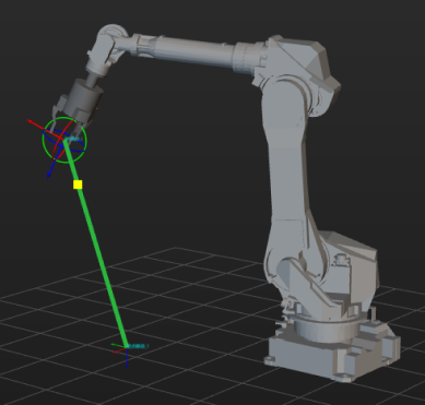
Motion Type
Robot motion usually refers to the process of moving the robot tool center point (TCP) from point A to point B in space. The joint motion and linear motion are two fundamental methods of robot motion.
Joint Motion
Joint motion is the motion of a robot achieved by adjusting the angle or position of each joint. Each joint can rotate or move to get the entire robot tool to an expected position.
Linear Motion
The linear motion is the motion of the robot tool on a linear path. Unlike joint motion, linear motion is achieved by moving the robot tool along a linear path.
Rotational Symmetry of the Target Object
A rotational symmetric target object will coincide with itself after rotating around its axis of symmetry.
Please refer to Rotational Symmetry for detailed description.
Rotational Symmetry of the Tool
A rotational symmetric tool will coincide with itself after rotating around its axis of symmetry.
Please refer to Rotational Symmetry of the Tool for detailed description.
Translational Relaxation
When some target objects are picked, the picking pose of the tool is allowed to be translated along the X-axis or Y-axis of the pick point, which is the translational relaxation.
Please refer to Translational Relaxation for detailed information.
Rotational Relaxation
When the robot picks certain target objects, the picking pose of the robot is allowed to be rotated flexibly within a specific angle range, which is the rotational relaxation.
Please refer to Rotational Relaxation for detailed information.
Master-Control Communication
Master-Control communication allows the vision system to control the robot to perform tasks. In this case, the vision system acts as the controller and the robot acts as the controlled party. Specifically, in the Master-Control communication, the vision system sends commands to the robot and the robot listens to, receives, and then executes the commands. For more information about the communication modes, refer to section Communication Modes.
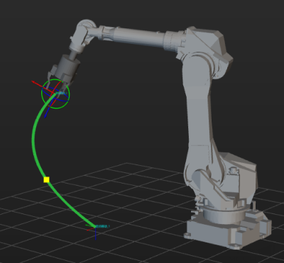
Path Planning
Calculates the optimal motion trajectory of the robot from the starting point to the target point, ensuring the generation of a safe, efficient, and collision-free path.
Simulation
Simulates the robot and its operation process in a virtual environment. Through the simulation of the robot motion and environment interaction, etc. on the software, we can verify motion trajectories, optimize the path planning and predict the risk of collision. The simulation process does not need to run a real robot.
Collision Detection
During the processes of simulation and path planning, the collision detection can recognize the potential collisions happened between robot and other objects in the working environment (including scene objects, target objects and the robot, etc), so as to optimize the path and ensure safe operations.
Robot Model
Digital models created according to real robot parameters (such as sizes, joint structures and kinematics characteristics) for simulation and path planning.