Use Model Editor to Create OBJ Models
The steps to convert STL models, STP models, STEP models, and ineligible OBJ models to OBJ models that are composed entirely of convex hulls are as follows.
1. Import Reference Model
Supported file formats of imported reference models include STL, STP, STEP, and OBJ.
| Excessively large model files can significantly increase import time and slow down path planning simulations. It is recommended to use graphics software to remove unnecessary features in advance and keep the file size under 100 MB. Additionally, ensure the model’s physical dimensions do not exceed 10 meters. |
Follow either of these steps to import the reference model.
-
Click and select the reference model file in the file selection window.
-
Drag and drop the reference model file to the interface of the Model Editor.
Select the unit according to the actual dimensions of the model in the pop-up window, and click OK.
| If an error message “Failed to load the model” pops up, please refer to Determine Whether the STEP/STP File Is Eligible to check the model file. |
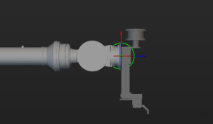
2. Set Frame (Optional)
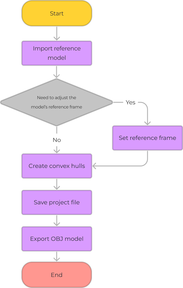
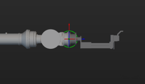
The end tool models with different poses in the Model Editor are illustrated in the table below, including the default pose that is assigned when the tool is initially added via the Tool Configuration window.
Pose of end tool model in the Model Editor |
Default tool pose when added via Tool Configuration |
|
|
|
|
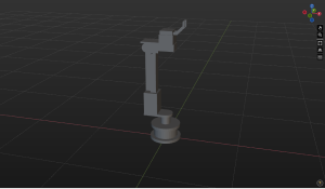
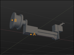
From the above table, we can see that if the installation position of the tool model on the robot’s end effector flange does not coincide with the “reference frame origin of the Model Editor’s world reference frame,” you should adjust the position or size of the end tool model when adding the end tool. To avoid the need for adjusting the model’s position every time it is used, please refer to the content in Adjust the Reference Frame of the Model to adjust the reference frame of the model.
|
A: The world reference frame origin of the Model Editor; B: The reference frame origin of the model installed location |
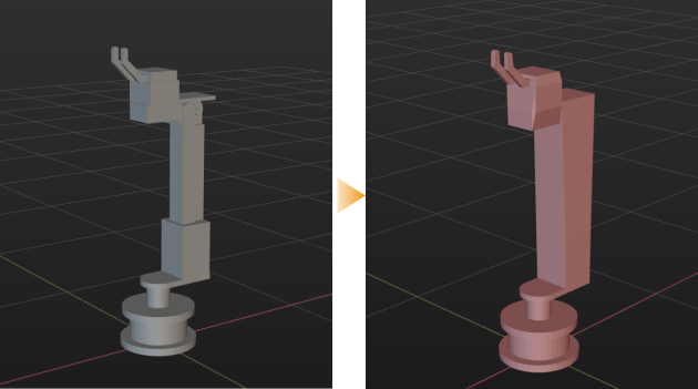
3. Create Convex Hulls
The collision models of tools used in Mech-Viz should be OBJ models that are composed entirely of convex hulls. A convex hull should be created based on the reference model. The final model should be composed entirely of convex hulls and reflect the shape of the original reference model.
There are two ways to create convex hulls, please select the one suitable for the actual model.
-
Use the selection tool to select vertices and create a convex hull based on the vertices.
-
Create a box or cylinder directly.
| Before proceeding to read the following content, please read Selection Tool Usage Guide and Create a Cuboid or Cylinder to learn about how to use the relative tools. |
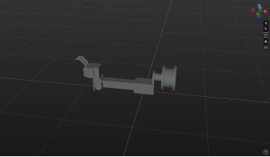
Do not use the 3D selection tool to cover the whole model to create a convex hull. It is recommended to segment the model into multiple parts according to its structure, and use the 3D selection tool to select each part and create convex hulls separately. For example, the model in the figure below can be segmented into 9 parts.
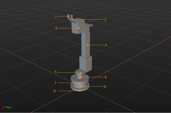
The steps are as follows:
-
Select the model name in the “Reference Model” panel, and click Selection Tool (Cuboid Selection, Cylinder Selection, or Elliptic Cylinder Selection).
-
Adjust the selection tool to cover the vertices on the part to be processed, and click Create Convex Hull.
-
Repeat step 2 until all 9 parts of the model are covered by convex hulls.
-
Click
 on the left of the reference model name to hide the reference model and view the convex model.
|
4. Save the Project File
To facilitate re-editing of the model, you can follow these steps to save the model to an M3D file.
-
Click .
-
Specify a save path and enter a file name.
-
Click Save.
5. Export the Model after Editing
Follow these steps to save the edited model to an OBJ file.
-
Click .
-
Specify a save path and enter a file name.
-
Save as type obj(*.obj).
-
Click Save.
Only the models set to visible in the Assemblies panel in the Model Editor will be saved, while the hidden ones will not be exported.
Once the model is exported successfully, you can add the model to Model library in Project resource tree. Then you can set the corresponding collision model of end tools in Tools.