Camera Cable Installation and Routing Guidelines
Camera Cable Connector Installation Guidelines
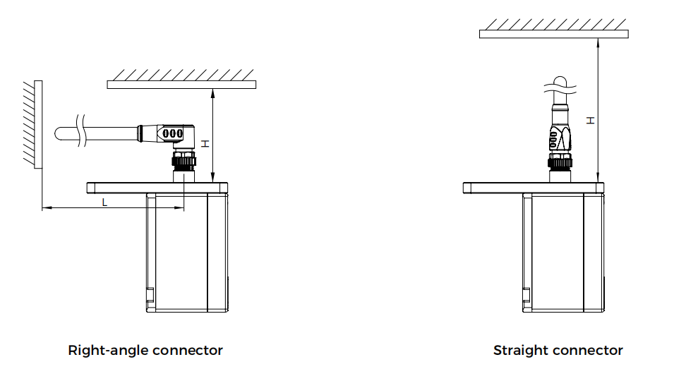
Considering the requirements for the disassembly and installation of cable connectors, the reserved space for the cables during camera installation should meet the following requirements:
-
Camera cable with a right-angle connector: H ≥ 70 mm; L ≥ 110 mm
-
Camera cable with a straight connector: H ≥ 130 mm
When mounting the camera in the eye in hand (EIH) mode, there are many cables at the end of the robot. In this case, the connectors should be protected from additional external force.

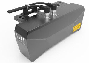
The following cable tie mount can be used on-site. For details on how to mount the cable tie mount, refer to Mount the Cable Tie Mount.
Camera Cable Routing Guidelines
Camera Cable Routing Guidelines in EIH Setup
To ensure the safety, reliability, and longevity of the camera cables, when routing the camera cables in an EIH setup, you should follow the guidelines on bending radius, twist angle, reserved cable length, cable securing, and cable protection.
Bending Radius Guidelines
Definition
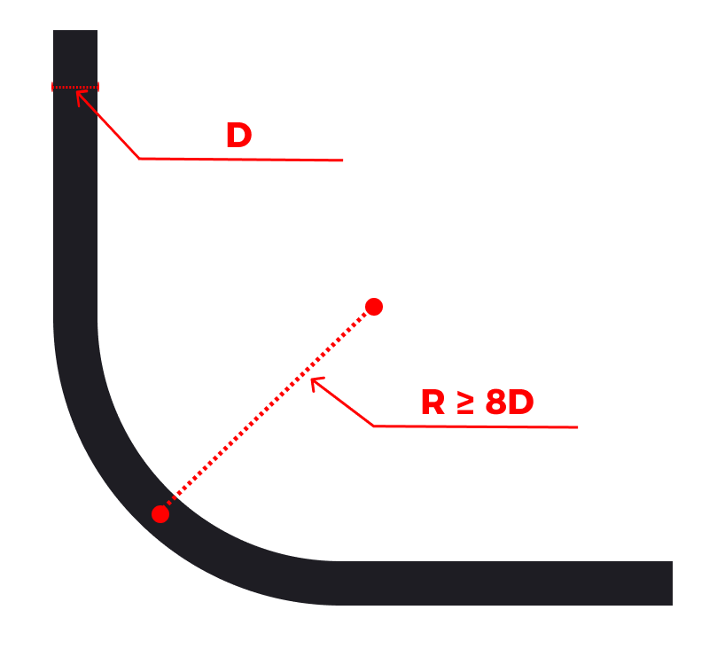
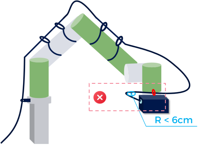
Bending radius refers to the distance from the outer side of the cable to the center of the bend when the cable is bent.
Requirements
-
The bending radius should not be less than 8 times the outer diameter of the cable (8D). You must strictly adhere to the guidelines to avoid excessive bending.
-
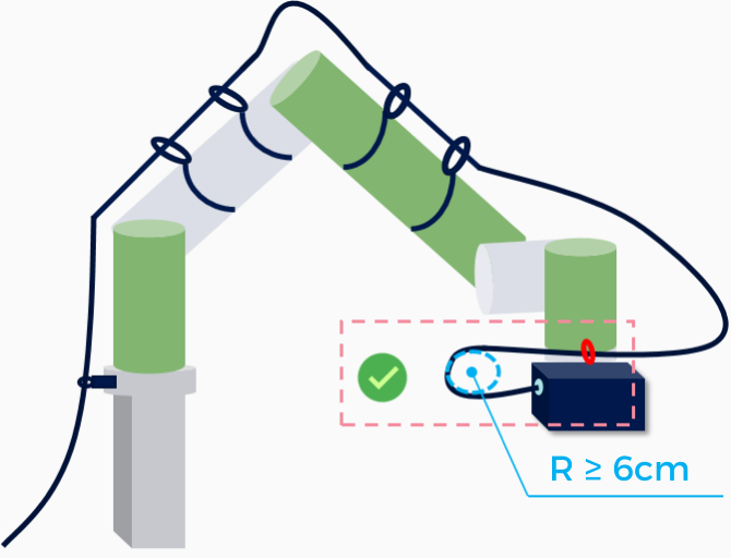
It is recommended that the bending radius of the camera cable should not be less than 6 cm.
-
Particular attention should be paid to the camera interface connection to prevent cable breakage or transmission damage caused by excessive bending.
Example
| Correct | Incorrect |
|---|---|
|
|
Twist Angle Guidelines
Definition
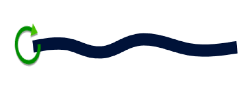
Twist angle refers to the degree of rotation of the cable around its own axis during routing. Excessive twisting can lead to stress concentration or damage to the cable’s conductor, insulation, or shielding.
Requirements
General requirement: The maximum allowable twist angle for the cable per meter is ≤ 180°.
Specific requirements:
-
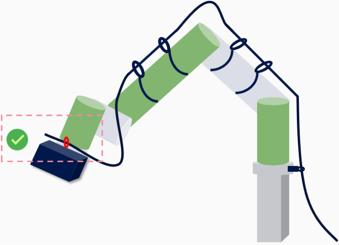
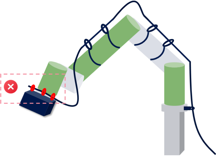
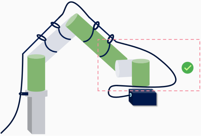
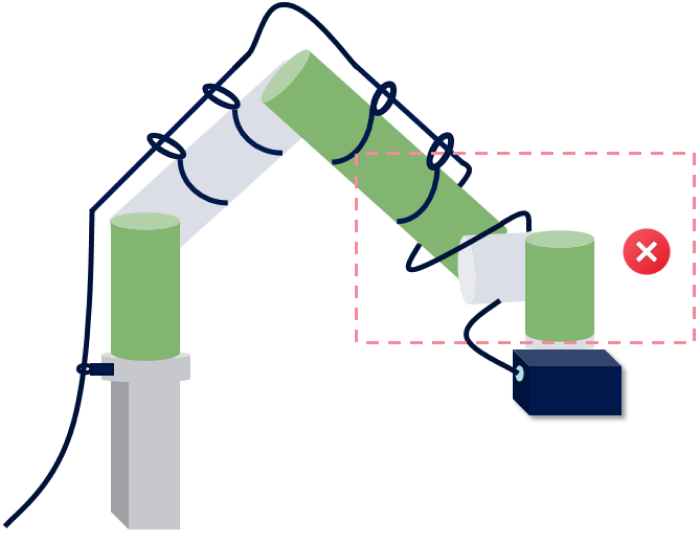
In the robot’s sixth axis, due to frequent rotation, cable ties should not be overly tight or numerous. Sufficient slack must be provided to avoid the accumulation of torque caused by the robot’s movement, which could lead to cable twisting or damage.
-
When the robot undergoes significant changes in posture, you need to ensure that, while maintaining compliance with the bending radius guidelines, the cables do not become entangled or subjected to tension during movement.
Test method
If you are unable to determine whether the cable’s twist angle complies with the guidelines, you can use the following testing method: loosen one end of the cable, allow it to naturally return to its original state, and observe the rotation angle during the straightening process.
Example
| Correct | Incorrect |
|---|---|
|
|
|
|
Cable Length Reserve Guidelines
Definition
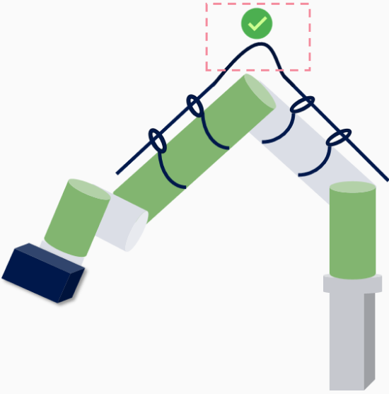
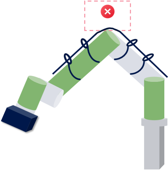
Cable reserve length refers to the additional length left during cable installation and routing to ensure subsequent adjustments, connections, maintenance, and replacement.
Requirements
In the parts of the robot where pulling forces are likely to occur during movement, sufficient cable length should be reserved to prevent the cable from being damaged by tensile stress.
Example
| Correct | Incorrect |
|---|---|
|
|
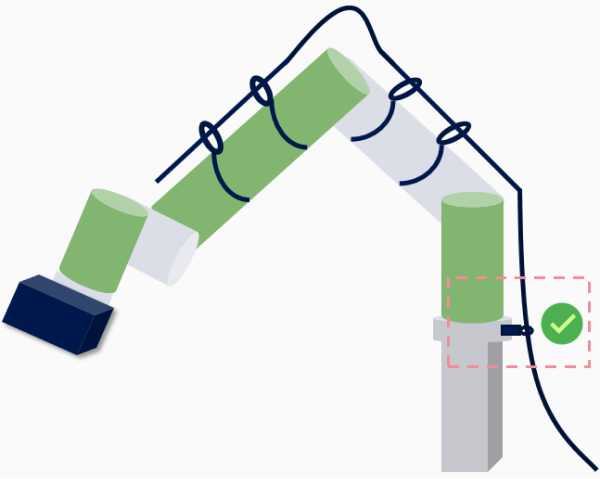
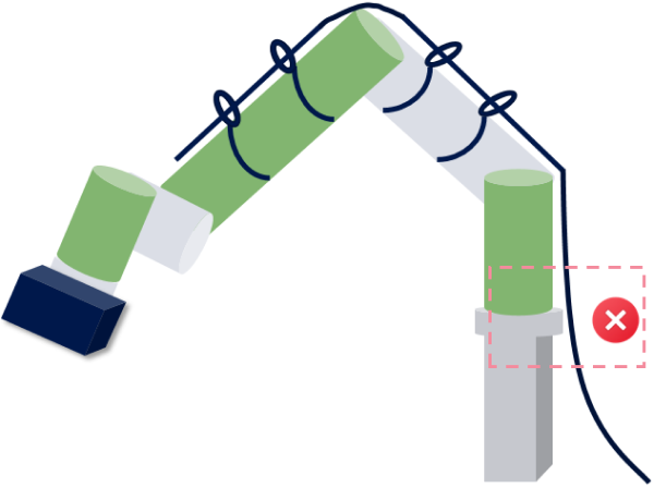
Cable Securing Guidelines
Definition
Cable securing refers to the use of proper support and fixation measures to ensure that the cable remains stable and reliable during installation and operation, unaffected by movement, stretching, or wear.
Requirements
At areas with significant stress (such as the high base where the robot is mounted), a load-bearing fixation point should be added to securely anchor the cable, preventing stress from the hanging position from damaging the cable.
Example
| Correct | Incorrect |
|---|---|
|
|
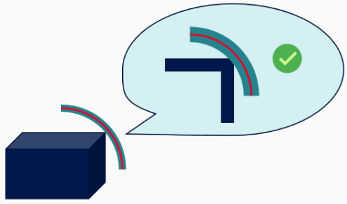
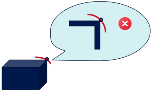
Cable Protection Guidelines
Definition
Cable protection refers to the use of various protective measures to ensure that the cable is protected from damage caused by external environments or mechanical stress during installation and use.
Requirements
-
you should avoid crossing cables and prevent cables from coming into contact with sharp objects to reduce wear and extend the cable’s service life.
-
In areas prone to damage, use protective conduits to further protect the cables from physical damage. At sharp corners, use spiral cable wraps for protection, but avoid using cable ties for securing, as this may cause wear on both the cable wrap and the cable itself.
Example
| Correct | Incorrect |
|---|---|
|
|
Camera Cable Routing Guidelines in ETH Setup
To ensure the safety, reliability, and longevity of the camera cables, when routing the camera cables in an ETH setup, you should follow the cable routing requirements below.
Length Optimization
When routing cables, the cable length should be optimized.
-
Design cable length reasonably: Plan the cable length properly according to the actual installation positions of the mounting frame and camera.
-
Reserve spare length: Leave extra length at the camera connector for location adjustments on the frame or future maintenance.
| Correct | Incorrect |
|---|---|

|
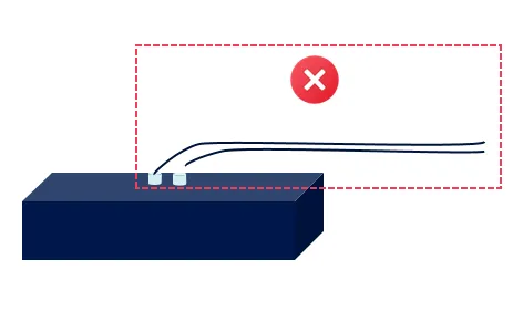
|
Slack Management
When routing cables, a certain amount of slack should be applied to meet the following requirements:
-
Avoid excessive tension: Ensure that the cables are not too taut during installation and maintain an appropriate amount of slack.
-
Prevent tension: Proper slack can prevent tension caused by frame displacement or vibration.
| Correct | Incorrect |
|---|---|

|

|
Compliance with Bending Radius Requirements
When routing cables, the following bending radius requirements should be observed:
-
Avoid sharp bends: Cables should follow the fixed path along the frame or installation structure, avoiding sharp bends or folding.
-
Meet bending radius requirements: The bending radius should not be less than 8 times the outer diameter of the cable (8D).

-
Ensure that the bending radius complies with design standards, especially at corners and near camera connectors.
-
Ensure that the bending radius requirement is met when the cable is too long and needs to be bundled.
-
| Correct | Incorrect |
|---|---|

|

|
Separating the Ethernet Cable from High-voltage Power Lines
When routing cables, ensure that the Ethernet cable is laid separately from high-voltage power lines to avoid electromagnetic interference. When using protective measures such as conduit, ensure that the two are kept apart to reduce signal transmission interference.
| Correct | Incorrect |
|---|---|
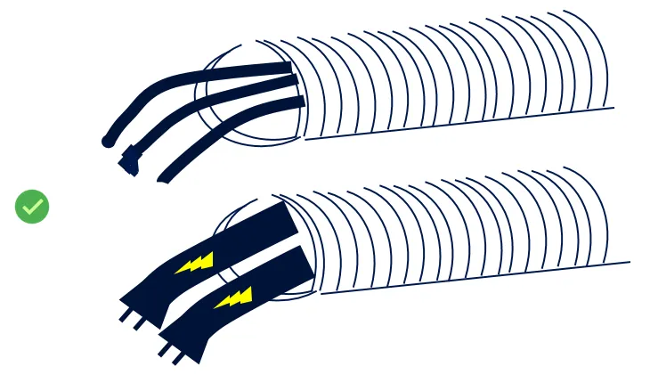
|
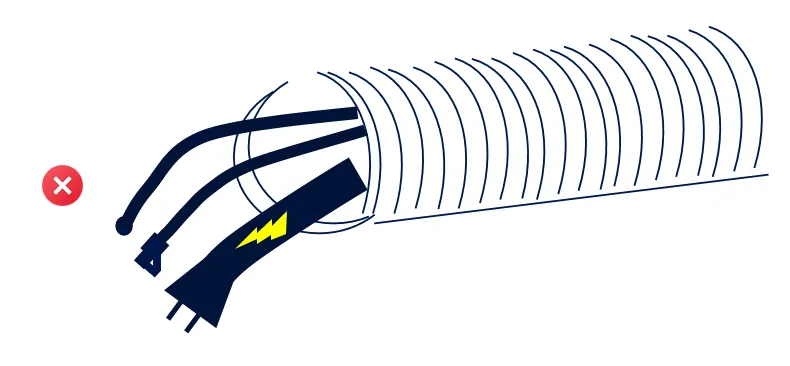
|
Summary
-
Systematic design: When designing the vision solution, the cable routing plan should be considered and integrated into the overall design.
-
Standardized routing: Cables should be routed according to the routing plan, following the routing guidelines.
-
Regular inspections:Ensure that a visual inspection is performed weekly to check the cable securing status, slackness, and connector joints. Ensure that there is no tension, wear, or looseness.
-
Record maintenance: Ensure that each inspection and adjustment is recorded for subsequent traceability and the optimization of the wiring plan.
-
Ongoing training: Provide regular training on routing standards and the latest technologies to relevant personnel to ensure consistency in standard implementation.
By strictly following the above guidelines and best practices, the reliability and performance of the camera cables can be significantly improved, reducing downtime caused by cable issues, and ultimately enhancing overall production efficiency.
Routing Requirements for Cables inside Dresspack or Track Chain
During cable routing, dresspack and drag chain (such as track chain) are two common cable protection devices. When routing cables inside a dresspack or track chain, adhere to the following requirements.
|
-
Avoid fixing the cables inside
Inside the dresspack or track chain, you should avoid fixing the cables to the internal structure to ensure they have sufficient freedom to move and bend, preventing any restriction of their normal movement. Please refer to the figure below for specific securing methods.
-
Fix the cables at the entrance to prevent friction
Secure the cables at the entrance of the dresspack or drag chain to prevent friction between cables.
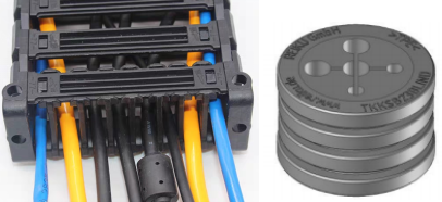
-
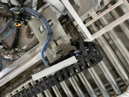
Ensure that a part of the track chain does not move with the camera
The general requirement is that at least 3 to 4 sections of the track chain do not move with the camera.
-
Avoid subjecting the cables in the track chain to additional tension
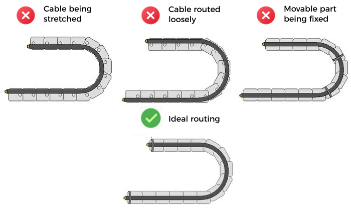
When routing cables inside the track chain, you should avoid subjecting the cables to excessive additional tension. The cables should not be pulled too tight (as shown in the left image), nor should they be too loose (as shown in the right image). Pulling the cables too tight or too loose can cause friction with the inner walls of the track chain, leading to wear on the protective sleeve. Additionally, excessive looseness can increase the risk of entanglement. In addition, if the moving parts of the cables are fixed, bending stress cannot be dispersed and absorbed, leading to stress concentration at the fixed points. Therefore, the cables should be fixed only at both ends of the track chain.
-
Prevent interference between cables inside the track chain
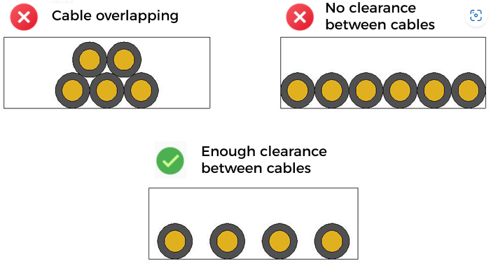
When routing cables inside the track chain, you should avoid overlapping cables and implement horizontal routing to prevent interference between cables. When implementing horizontal routing, ensure there is enough clearance between the cables. Inside the track chain, the clearance between cables should be at least 10% of the cable diameter to ensure that each cable has enough space and does not come into contact or friction with others.
-
Avoid cable knots and tangling inside the corrugated tube
When routing cables inside the corrugated tube, ensure that the cables do not knot or tangle, to prevent friction or damage caused by cable entanglement.