Understand Control Flow
This chapter will introduce the control flow in the Mech-Vision Steps, as well as how to use the control flow.
In Mech-Vision, the standard data flow follows a top-to-bottom direction according to the workflow you created. Additionally, you can configure the control flow to trigger other Steps or the workflow. If the current Step is connected with a control flow, it will run only when that control flow is triggered. Otherwise, the Step will not run.
As shown in the figure below, there are two vision processing workflows in the vision project, with red arrows representing the control flow. When the control flow is not triggered, the workflow D → E → F is executed. When it is triggered, both the D → E → F workflow and the A → B → C workflow are executed simultaneously.

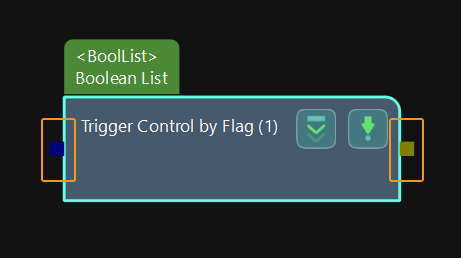
In the graphical programming workspace of Mech-Vision, once the Step is selected, the points displayed on both sides are the control flow connection points. The connection point on the left can be connected with input control flow, which triggers the execution of this Step. The connection point on the right can be connected with output control flow, which triggers the execution of other Steps.
|
In actual application, you can connect the input and output control flow respectively according to actual requirements.It is not required to connect both the input and output control flow. |
The following will introduce three common usages of the control flow.
Trigger Control by Flag
When configuring a vision project, it is common to add “branches” to the project, where each branch corresponds to a different vision processing flow. Then, based on different rules, different branches are triggered to execute various vision processing flows in different situations.
The Trigger Control by Flag Step is usually used to trigger the control flow. This Step is often used in conjunction with the Step that outputs a Boolean value, such as the Dichotomize Values by Threshold Step.
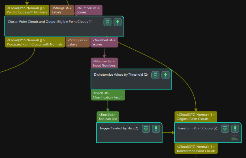
The vision processing flow shown in the figure below demonstrates the process of transforming point clouds when their confidence level meets specified requirements. Here is detailed description of each Step in this process.
-
The “Cluster Point Clouds and Output Eligible Point Clouds” Step outputs the confidence of point cloud.
-
The Step “Dichotomize Values by Threshold” evaluates whether the confidence of the previous Step’s point cloud exceeds the set threshold. If it exceeds the threshold, the Boolean value is False; otherwise, it is True.
-
The Step “Trigger Control by Flag” receives the Boolean result from the previous Step and triggers the “Transform Point Clouds” Step accordingly. Afterwards, the subsequent Steps continue to execute.
Trigger Control Flow Given Output/Given No Output
When running a vision project, there may be a Step producing no output. In cases where the vision project comprises multiple vision processing flows, one can trigger the execution of another “branch” through relevant settings. Similarly, it is also possible to trigger the execution of another “branch” when a Step produces output.
During the configuration of the project, you need to select Trigger Control Flow Given Output or Trigger Control Flow Given No Output for the Step used to trigger the control flow in the Execution Flags first.
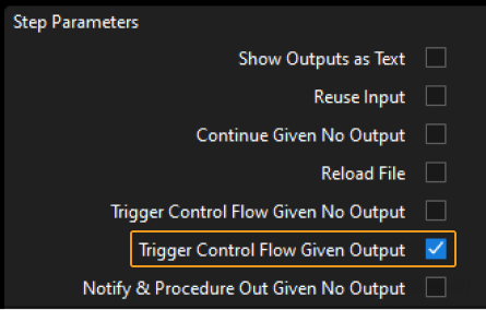
For example, when you select Trigger Control Flow Given Output, which is shown below, the Step “3D Matching” will trigger the execution of the “Point Filter” Step after it produces output, and then the project will run the subsequent Steps.
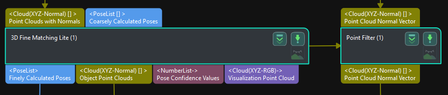
|
After selecting Trigger Control Flow Given No Output for the “3D Target Object Recognition” Step, the control flow will still be triggered even if the output of the Step is empty. |
Use Control Flow to Disable Other Irrelevant Steps
In actual projects, some Steps may become unnecessary due to hardware updates or other related factors. However, for future possibilities or the need to document historical operations, it may still be desirable to retain these Steps. In such cases, you can use control flow to disable these Steps that are irrelevant to the current requirements, ensuring the flexibility and traceability of the project.
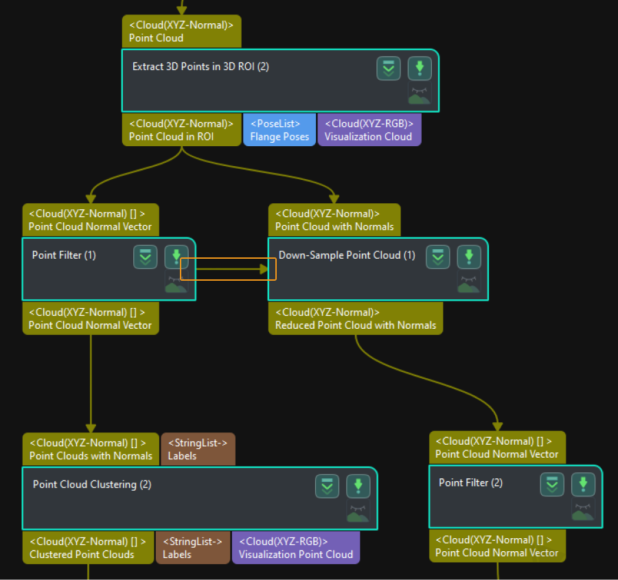
As shown in the figure below, if you want to skip the “Down-Sample Point Cloud” Step and directly execute the “Point Filter” Step and subsequent Steps, you can add the “Point Filter” Step on the left and connect the output control flow to the “Down-Sample Point Cloud” Step. This effectively disables the vision processing flow on the right, so that when you run the project, only the left-side vision processing flow will be executed.
|
When you use control flow to disable the irrelevant Steps, there is no need to select Trigger Control Flow Given Output or Trigger Control Flow Given No Output for the Step used to trigger the control flow in the Execution Flags first. |