Create and Import Robot Model
When the robot model library does not include the robot you need, the basic procedures for creating and importing a robot model are shown below.
A FANUC M-900iB/400L robot will be used as an example.
|
If the robot brand you want to import is not available in the Robot Model Library, please refer to How to Import Robot Models from Other Brands?. |
Obtain the CAD File and Specifications of the Robot
Before creating the robot model, please obtain the CAD file and the datasheet which contains DH parameters and motion ranges of each joint of the robot.
You can download the relevant documentation on the official website of the robot.
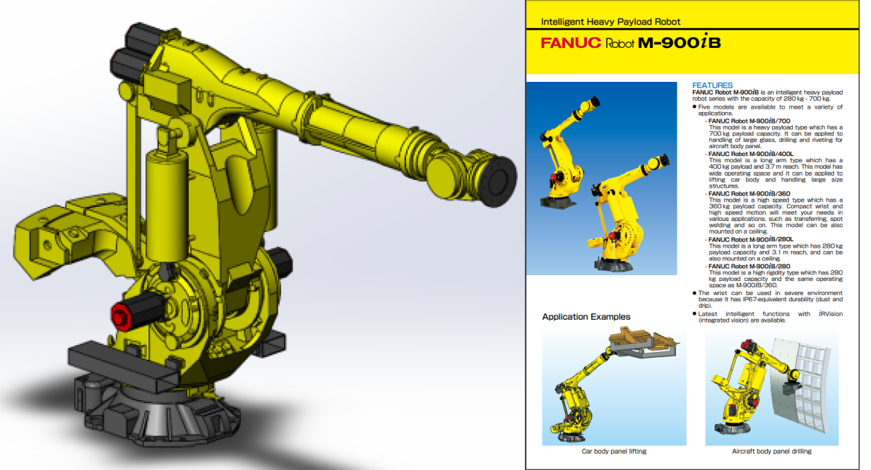
The figure below shows the CAD model and descriptions of FANUC M-900iB/400L.
| Some robot websites will provide models in X_T format. Comparing to STEP files, X_T files perform better and takes less time in reconstruction. Therefore, it is recommended to use models in X_T format. |
Determine the Robot Configurations and Write the Parameter Files
After confirming the robot’s configuration by referring to its CAD model and manual, create the corresponding parameter file.
Obtain the Configuration of the Robot (algo_type)
Different robots have different configurations which are described by different frames of reference and DH parameters.
Please refer to Robot Configurations for examples of different robot configurations.
FANUC M-900iB/400L is a common 6-axis split-ball type wrist industrial robot, which belongs to the SphericalWrist_SixAxis configuration.
Obtain the DH Parameters (dh, dhPassive)
Please refer to Robot Configurations and find the corresponding configuration file of the robot. Then you can confirm the DH parameter value in [robot]_algo.json according to the DH parameters in the specifications of the robot.
The DH parameters of FANUC M-900iB/400L are a=0.940, b=0.410, c=1.120, d=0.250, e=2.180, f=0.300.
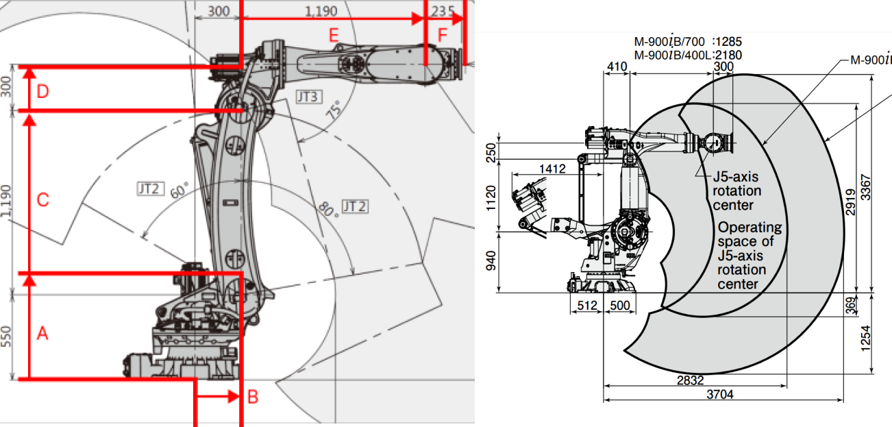
In the above figure, the configuration diagram of SphericalWrist_SixAxis robot is on the left, and the specifications of FANUC M-900iB/400L is on the right.
Obtain the Motion Ranges of Each Joint (minlimits, maxlimits)
Usually, the motion ranges of joints are specified in the documentation of the robot. However, you need to open the robot simulation software RoboGuide of FANUC robots and then search for the motion ranges in this case.

Obtain Other Parameters
For common robot brands, you can refer to the parameters of other created robot models. If there are not available parameters to reference, please contact the site engineers for other parameters, i.e., mastering_joints, axis_flip, base_z_offset, axis_flip, and mastering_joints.
|
Write the [robot]_algo.json File
The template file algo_example.json is stored in C:/Users/Administrator/AppData/Roaming/Mmind/Robot Library 2.0. You can create a new [robot]_algo.json file based on the template.
| For the definition of the parameters in the [robot]_algo.json file, please refer to Description of [robot]_algo.json File. |
Write the [robot]_profile.json Parameter File
The template file profile_example.json is stored in C:/Users/Administrator/AppData/Roaming/Mmind/Robot Library 2.0. You can create a [robot]_profile.json file based on the template.
| For the definition of the parameters in the [robot]_profile.json file, please refer to Description of [robot]_profile.json File. |
Use Solidworks to Construct a STL Model of the Entire Robot
Import the CAD Model in SolidWorks
Open the CAD model of the robot in SolidWorks, as shown below.
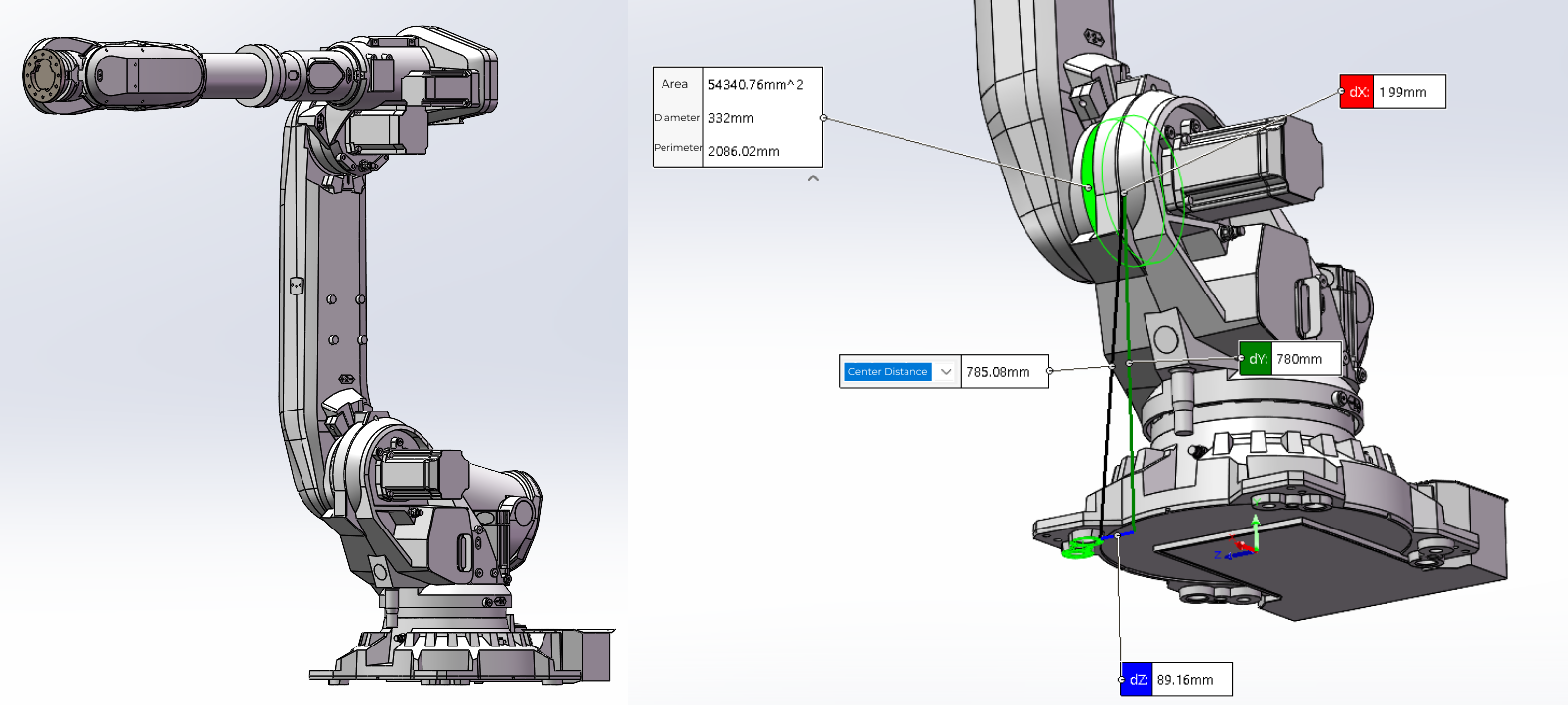
In the above figure, the CAD robot model is on the left and an assembly reference diagram is on the right.
|
Create Reference Frames
Please refer to Robot Configurations to create the reference frame of each axis.
As for FANUC M-900iB/400L, the configuration is SphericalWrist_SixAxis, and the robot pose should be like the figure below: J1 axis is aligned with the base, J2 axis stays vertically upward, J3 axis and J4 axis stays horizontally forward, and J5 axis stays forward rather than downward. Once the pose is determined, all parts should be fixed.

Export STL Models of Robot Joints
It is recommended to hide other parts on the assembly when exporting the joint model in turn.
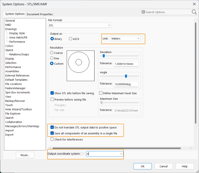
Save the exported file in STL format, set the output to binary and the unit to meter. Please refer to Robot Configurations for detailed information. Other settings are shown below.
The entire robot model of FANUC M-900iB/400L in STL format is shown below.
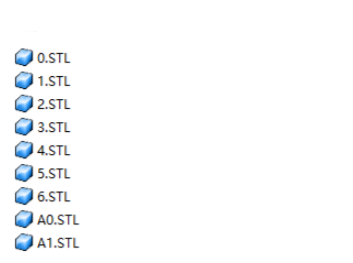
Now you have completed creating a robot model.
Import the Robot Model to Mech-Viz
After creating the robot model, please import the robot model to the robot model library of Mech-Viz for further use.
Follow the steps below to import the robot model to Mech-Viz:
-
You can open the folder containing the robot model using either of the following methods.
-
In the Robot Model Library, right-click any robot model card, and then select “Open robot model folder” in the context menu.
-
In the project resource tree, right-click the robot name, and then select “Open Robot File Directory” in the context menu.
-
-
Navigate to the robot brand folder within the robot model file directory.
The robot model of Mech-Viz is stored in the
C:\Users\<UserName>\AppData\Roaming\Mmind\Robot Library 2.0file. Robot models of the same brand are stored in the same folder which is named after the brand name, and all the files of the robot model are stored in the folder which is named after the model name. -
In the robot brand folder, create a new folder for the specific robot model—for example, fanuc_m900ib_400l.
Use lower case letters to name the folders.
-
Store all model and parameter files in the designated path to import the robot model to Mech-Viz.
-
The supported robot model formats include STL, DAE, and OBJ, and files of each format should be stored in their respective folders.
-
STL model can be used for both visualization and collision detection.
-
DAE model can only be used for visualization.
-
OBJ model can only be used for collision detection.
-
A complete robot model should include at least one visualization model and one collision model.
For example, for a FANUC M900iB/280L robot, the corresponding model folder is located at
C:\Users\<UserName>\AppData\Roaming\Mmind\Robot Library 2.0\fanuc\fanuc_m_900ib_280l. The folder structure is shown in the figure below.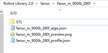
STL
Model file
fanuc_m900ib_280l_algo.json
Robot kinematics parameter file
fanuc_m900ib_280l_preview.png
Robot picture
fanuc_m900ib_280l_profile.json
Robot kinematics parameter description file
-
-
Go back to the Robot model library, and you can find and select the imported robot model.
Verify Robot Model Parameters
Before the actual deployment of the project, you need to verify the robot model parameters. If there is a big difference, such as 1 to 2 meters, between the simulated robot pose and TCP in the software and the real robot pose, it indicates that the robot model parameters may be inaccurate and need to be corrected.
For detailed instructions, see the Guide for Robot Model Parameter Verification.