Tools
This section introduces tools and corresponding configurations.
Introduction
Tools, such as grippers and suction cups, are mechanical devices attached to the end of the robotic arm to perform various tasks. The tool model and configuration are used not only for 3D simulation and path planning, but also directly affect the robot’s motion accuracy and operational reliability during an actual run.
| When running the Mech-Viz project, you need to add picking configuration when setting the pick point in the Target Object Editor to enable the corresponding tool for the pick point. If it is not enabled, an error will occur during simulation or path planning: “The pick point does not match the tool”. |
Model of the Tool
In order to visualize the tool in the 3D simulation area and make the tool involve the collision detection, you need to create a visualization model and a collision model of the tool and import them to the model library.
The following table shows the formats of the supported visualization model and collision model of the tool.
Format |
STL |
OBJ |
DAE |
Binvox |
Visualization Model |
√ |
√ |
√ |
× |
Collision model |
√ |
√ |
× |
× |
|
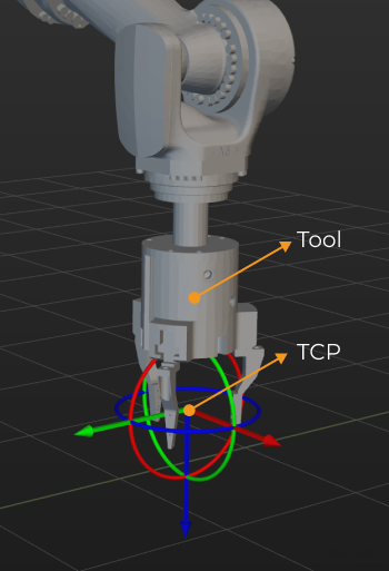
Tool Center Point (TCP)
The tool is used to pick and place the object. When you move the robot to a specified point to perform pick-or-place task, you are actually moving the TCP (Tool Center Point) to that point. The default TCP is located at the end of the robot, but sometimes you need to adjust the TCP to ensure that the TCP is at the right place for the actual pick-and-place process.
Configure the Tool
Import the Collision Model and Visualization Model
Click the + next to , and select the collision model and visualization model in the pop-up window, and then click Open.
Add the Tool
Go to and click + to open the Tool Configuration window.
-
Enter a Tool name.
-
Select the Tool type according to the actual situation. When a depalletizing vacuum gripper is used, please configure depalletizing vacuum gripper.
-
Select the Collision model in the drop-down list.
-
Select the Visualization model for the visualization in the 3D simulation area. When the position or size of the visualization model is not correct, please refer to Adjust the Position or Size of the Tool Model to adjust the model.
-
According to actual situations, you can set the Rotate to pick parameter as Disable rotation or Enable rotation for picking. If you choose to select Enable rotation for picking, please set Number of attempts. Configuring the rotation for picking can prevent the robot’s end tool from unnecessary rotations during picking and placing. This increases the success rate of path planning and reduces the time required for path planning, allowing the robot to move more smoothly and swiftly.
360°/Number of attempts = The tool’s rotation angle each time -
Follow either of the methods below to set the TCP.
Update TCP from robot
Obtain TCP by TCP calibration
Enter the TCP using Euler angles, quaternions, or rotation vectors.
If you have already obtained the accurate TCP by other methods, you can click Edit pose and paste the data in the pop-up window.
-
Click OK in the end.
If you need to add more tools, please repeat the above steps.
Delete the Tool
Follow either of the following steps to delete the tool.
-
Go to , select the tool name and press the Delete key.
-
Go to , right-click the tool name and select Delete in the context menu.
Modify the Tool
-
Follow either of the following steps to open the Tool Configuration window.
-
Go to , double-click the tool name.
-
Go to , right-click the tool name and select Tool Configuration in the context menu.
-
-
Modify the parameters according to the actual requirement.
-
Click OK.
Set as Active Tool
If you only add one tool, the current tool is the active tool.
If you add multiple tools, the first added tool will be used as the active tool by default.
To set a tool as active tool, go to , right-click the tool you want to use and select Set as Active Tool.
Adjust the Position or Size of the Tool Model
Follow the steps below to adjust the tool model when its position is not correct.
-
Double-click the tool model under .
-
Adjust the pose parameters in the pop-up Edit Model Transform window to adjust the model’s position in the 3D simulation area.
Follow the steps below to adjust the model when its size is not correct.
-
Double-click the tool model under .
-
In the pop-up Edit Model Transform window:
-
Adjust the Scale if you want to adjust the scale of the entire model.
-
If you want to adjust the scale on the individual X, Y, or Z direction, clear the Keep ratio for X,Y,Z checkbox, and adjust the scale on each direction respectively.
-