Set Step Parameters
Global Configuration
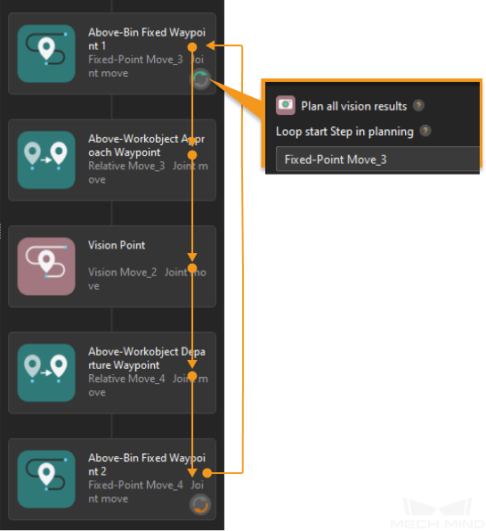
Plan all vision results
Once this option is enabled, the current workflow will be looped until all received vision results are used for the path planning, and then all paths for picking can be output after the planning is completed. You should set a Loop start Step in planning if this option is enabled.
| The “planning” refers to the process when the software attempts to find a collision-free path that the robot can follow to reach the target position. |
The Loop start Step in planning is the Step where the loop starts in the planning. For example, “Fixed-Point Move_3” is set as the Loop start Step in planning in the figure below, and the software will loop the current workflow until all received vision results are used for the path planning.
Avoid picking on same target object
This option is used to avoid attempting repeatedly on the same pick point after a picking attempt fails.
Box depalletizing
Once this feature is enabled, the software will enter the depalletizing mode in which the end tool should be set to the depalletizing vacuum gripper. Please select the depalletizing method according to the requirement of the actual scenario.
| Once the box depalletizing feature is enabled, the point cloud of the target box will be removed by default, with an XY-direction point cloud removal range expansion of 10 mm and Z-direction point cloud removal range expansion of 30 mm. For detailed introduction to this feature, please refer to Remove Point Cloud of Target Object. |
Single-pick depalletizing
“Single-pick depalletizing” indicates that only one box will be picked at a time during depalletizing.
Please follow these steps to configure:
-
Go to the project resource tree and click + on the right of Tools to open the Tool Configuration window.
In this window:
-
Select Depalletizing vacuum gripper as the Tool type.
-
Click the Configure depalletizing vacuum gripper button at the bottom to open the vacuum gripper configurator. You can refer to Depalletizing Vacuum Gripper Configuration to complete the configurations.
-
-
Enable Box depalletizing in the Global configuration.
-
Select Single-pick.
-
Set the Min box surface coverage parameter according to the actual situation.
This parameter specifies the minimum proportion of a box’s upper surface covered by the vacuum gripper when the vacuum gripper attempts to pick a box. If the coverage is larger than the value, it is considered that the vacuum gripper is able to pick the box.
Multi-pick
“Multi-pick” indicates that boxes will be automatically grouped for depalletizing, and a box group containing multiple boxes will be picked altogether at a time.
Please follow these steps to configure:
-
Click the plus sign next to “Tools” in the resource tree to open the Tool Configuration window.
-
Select Depalletizing vacuum gripper as the Tool type.
-
Click the Configure depalletizing vacuum gripper button at the bottom to open the vacuum gripper configurator. You can refer to Depalletizing Vacuum Gripper Configuration to complete the configurations.
-
-
Enable Box depalletizing in the Global configuration.
-
Select Multi-pick depalletizing.
-
You can set the following parameters according to the actual requirements.
-
Min box surface coverage
This parameter specifies the minimum proportion of a box’s upper surface covered by the vacuum gripper when the vacuum gripper attempts to pick a box. If the coverage is larger than the value, it is considered that the vacuum gripper is able to pick the box.
-
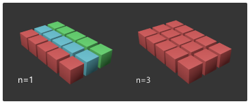
Max rows per group
The allowable maximum number of rows in one box group for multi-pick depalletizing.
-
Spacing upper limit
This parameter limits the maximum distance between two adjacent boxes in the grouping direction. When the distance is smaller than this value, the boxes can be considered to be in a group.
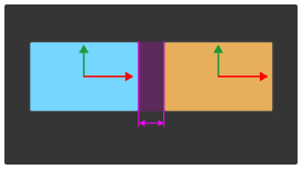
Please note that the value of this parameter cannot be greater than the box width in the vision result. If the set value is greater than the box width, the value will be automatically modified to the box width in the actual execution. -
Deviation upper limit
This parameter limits the maximum deviation distance of a box in the direction perpendicular to the grouping direction. When the deviation distance is smaller than this value, the box can be considered to be in the group.
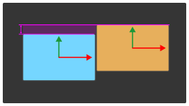
Please note that the value of this parameter cannot be greater than the box width in the vision result. If the set value is greater than the box width, the value will be automatically modified to the box width in the actual execution. -
Angle deviation upper limit
This parameter limits the angle of rotational deviation of a box relative to the grouping direction. When the rotation angle is smaller than this value, the box can be considered to be in the group.
-
Fixed-Point Move
This Step specifies a fixed pose as the waypoint.
Parameter Description
-
Whether to send to robot
Description: Determine whether to send the pose of this Step to the robot.
Example: If Plan and not send is selected, the Path Planning Step will not output the pose of this Step.
-
Motion type
Description: The motion type in which the robot moves to the corresponding pose in this Step. The linear move is typically used in gluing scenarios.
Example: If joint move is selected, the robot will move to the corresponding pose in this Step with the joint movement.
-
Robot pose type
Description: Select the method to adjust the pose.
You can adjust the robot pose in one of the three ways below.
-
Adjust the JPs of the robot.
-
Drag the pose manipulator in the 3D simulation area.
-
Enter the pose of the real robot.
-
Move the robot with the teach pendant and record the TCP or joint positions.
-
Click Edit pose (if the robot pose is in the form of TCP) or Edit JPs (if the robot pose is in the form of Joint positions) in the Robot panel.
-
Enter the recorded TCP or JPs and click OK. Then the simulated robot will move to the corresponding pose.
-
Relative Move
This Step specifies the distance the robot moves along the Z-axis relative to the previous or next waypoint.
Parameter Description
-
Whether to send to robot
Description: Determine whether to send the pose of this Step to the robot.
Example: If Plan and not send is selected, the Path Planning Step will not output the pose of this Step.
-
Motion type
Description: The motion type in which the robot moves to the corresponding pose in this Step. The linear move is typically used in gluing scenarios.
Example: If joint move is selected, the robot will move to the corresponding pose in this Step with the joint movement.
-
Move relative to
Description: The reference pose when the robot moves.
Example: If Previous waypoint is selected, the robot will move based on the previous waypoint.
-
Direction
Description: The direction along which the robot moves.
Example: If Along target object frame Z-axis is selected, the robot will move along the Z-axis of the target object reference frame.
-
Distance
Description: The distance that the robot moves along the direction of movement.
Vision Move
This Step is used to pick the target object. The vision points input to the Path Planning Step will be used in this Step.
Parameter Description
-
Whether to send to robot
Description: Determine whether to send the pose of this Step to the robot.
Example: If Plan and not send is selected, the Path Planning Step will not output the pose of this Step.
-
Motion type
Description: The motion type in which the robot moves to the corresponding pose in this Step.
Example: If joint move is selected, the robot will move to the corresponding pose in this Step with the joint movement.