Custom Pallet Pattern
Function
Use the pallet pattern customized in the Pallet Editor.
Usage Scenario
This Step applies to scenarios in which the pallet patterns are not symmetric and irregular.
Parameter Description
Move-Type Step Common Parameters
Send Waypoint
Selected by default, i.e., send the current waypoint to the receiver, such as the robot. Once deselected, the current waypoint will not be sent. However, the waypoint will remain in the planned path.
Try Continuously Running through Succeeding Non-Moves
Unselected by default. When non-move Steps, such as Visual Recognition, Set DO, Check DI, etc., are connected between move-type Steps, the sending of the waypoints will be interrupted, and the real robot will take a short pause, reducing the smoothness of running.
When this parameter is selected, the project will continue to run without waiting for the current move-type Step to complete execution, and therefore the robot can move in a smooth way without pauses. However, selecting this parameter may cause the execution of the Step to end prematurely.
Why will this feature cause the execution of the Step to end prematurely?
Mech-Viz will send multiple waypoints simultaneously to the robot when the project is running. When the currently returned JPs of the robot correspond to the last waypoint sent by Mech-Viz, Mech-Viz will assume that the robot has moved to the last waypoint.
For example, there are 10 move-type Steps in a path, and the pose of the 5th move-type Step is the same as that of the last move-type Step. When the robot moves at a low speed, the current JPs will be sent to Mech-Viz after the robot moves to the 5th waypoint. Since the poses of the 5th move-type Step and the last move-type Step are the same, Mech-Viz may mistakenly determine that the robot has reached all waypoints and prematurely ends the command.
Do Not Check Collision with Placed Target Object
Once Detect collisions on target objects is enabled in the Collisions panel, selecting this parameter will disable the collision detection between the robot, robot tool, and placed target objects. Typically, this parameter is selected in the move-type Step following the Step whose Pick or place is set to Place to avoid false collision detections.
Application Example:
The TCP of a depalletizing vacuum gripper is usually set inside the model rather than on the surface of the vacuum gripper. As a result, when picking a box, the vacuum gripper model may overlap with the box model. However, the software does not detect collisions between the end tool and the picked target object, so no collision alarm will be triggered during picking. Once the robot places the box down, the picked box model becomes a scene model, and the software will start to detect the collision between the end tool and the box’s scene model, triggering a collision alarm and preventing the completion of the palletizing task.
Once this parameter is selected, no collision between the robot, end tool, and the model of the placed target object will be detected, and the above issue will be resolved.
Point Cloud Collision Detection Mode
Usually, Auto can be selected, i.e., directly apply the Point cloud collision detection settings in the Collisions panel. For the Steps between picking and placing, Check collision can typically be selected.
Auto |
Default setting. Once Detect collisions on target objects is enabled in the Collisions panel, only point cloud collisions of the “Vision Move” Step and the “Relative Move” Steps that depend on the “Vision Move” Step will be detected, while other move-type Steps will not be detected. |
Do not check collision |
Point cloud collisions of all move-type Steps will not be detected. |
Check collision |
Point cloud collisions of all move-type Steps will be detected. |
Ignore Target Object Symmetry
This parameter is only visible when the Waypoint type of the move-type Step is set to Target object pose.
The target object symmetry here refers to the Rotational symmetry of held target object predefined in the target object editor during collision model setup.
None |
Default setting, i.e., do not ignore symmetry on any axis. |
Around target object frame Z axis |
Only ignore symmetry around the Z-axis. |
Around target object frame X&Y axes |
Ignore symmetry around the X-axis and Y-axis. |
Around all axes |
Once the symmetry around all axes is ignored, the robot will place the object strictly according to the target object pose. |
| When the move-type Steps are used to place the target objects, the consistency of the placing poses of the target objects cannot be guaranteed once the rotational symmetry is applied. If you want all target objects to be placed strictly according to a specific rule, ignore the symmetry of the target object around all axes. |
Plan Failure Out Port
Once this parameter is selected, a Plan failure exit port will be added to the Step.
If the path planning of the current Step succeeds, the workflow will continue along the Success exit port. If the path planning of the current Step fails, the workflow will proceed along the Plan failure exit port. If multiple move-type Steps with “Plan failure” exit ports display in the same plan history entry, the workflow will proceed along the “Plan failure” exit port of the first move-type Step.
Held Target Object Collision Detection Settings
Before configuring this parameter group, please go to the Collisions panel and enable Detect collisions on target objects.
| Disabling collision detection will increase the collision risks. Please select the following parameters with caution. |
Do Not Check Collision with Scene Objects
Once this parameter is selected, collisions between the held target object and the scene model will not be detected, reducing the computational load of collision detection in the software, speeding up path planning, and optimizing the overall cycle time.
Do Not Check Collision with Robot
Once this parameter is selected, collisions between the held target object and the robot will not be detected, reducing the computational load of collision detection in the software, speeding up path planning, and optimizing the overall cycle time.
Do Not Check Collision with Point Cloud
Once Point cloud collision detection is enabled in the Collisions panel, selecting this parameter will stop detecting collisions between the held target object and the point cloud, further reducing the software’s computational load, shortening path planning time, and enhancing the overall cycle time.
Index
Basic Pallet Settings
Entry Adjust
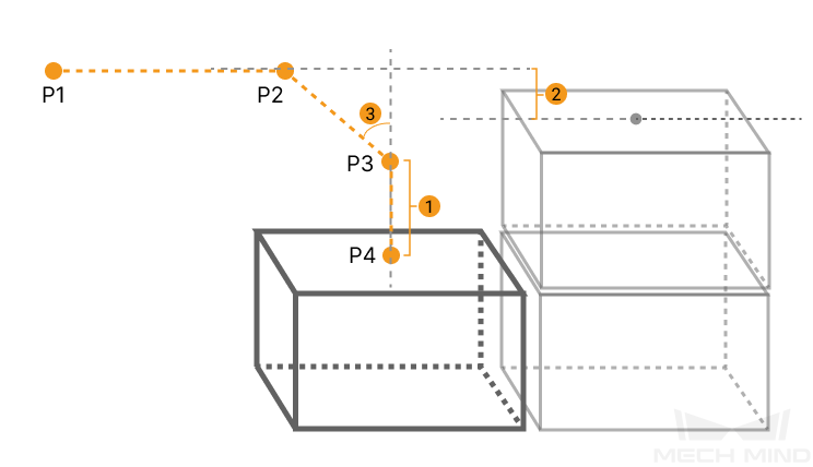
The three parameters together determines the path along which the robot enters the stack area. Adjust the entry path to make the held box approaches the palletized boxes at a specified angle, and then the held box will be placed vertically. If the box is directly placed on the stack in a vertical path, collisions may occur between the robot, held box, and the palletized boxes possibly due to accuracy and other factors.
For each box, there are four points to enter the stack area. This parameter determines three points: entry point (P2); adjustment point (P3); and placement point (P4).
|
1: Vertical Adjust Length; 2: Vertical Margin; 3: Entry Angle Z |
| Parameter | Description |
|---|---|
Vertical Adjust Length Ratio |
As shown in the right figure, vertical adjust length ratio = vertical adjust length (1) / the height of the box. |
Value range: 0–1; recommended value: 50%. |
|
Vertical Margin |
As shown in the right tag 2. |
Value range: 0–+∞; unit: mm; the specified values depend on different application scenarios. |
|
Entry Angle Z |
As shown in the right tag 3. |
Value range: -80°–80°; recommended value: 30°–45°. |
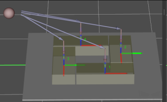
Auto Middle Point
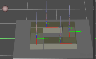
The Auto Middle Point is the direction indication of entering into the stack area, not the actual point reached by the robot. To avoid squeezing and collisions during the placement of boxes, the auto middle point should be as far away from the pallet as possible to ensure adequate safety spacing.
X/Y
The X/Y-coordinate of the reference sphere in the world reference frame. The reference sphere (the small pink ball in the 3D simulation area) determines the position of the auto middle point.
Minimum Height Z
The minimum height in the Z-direction of the robot entering into the entry section (the purple path).
Maximum Height Z
The maximum height in the Z-direction of the robot entering into the entry section (the purple path).
Keep Entry Segment Vertical
|
|
Unselected by default, i.e., the robot will approach the stack from the auto middle point. |
After selecting, the robot will approach the stack in a direction perpendicular to the pallet. |
Extended Distance For Entry
This parameter is used to extend the distance for entry.
When the tool is larger than the object being picked, the default entry path may not be long enough, resulting in a collision between the tool and placed boxes. In this case, extending the distance for entry can improve safety, avoiding the collision between the robot and placed boxes or other barriers in the process of robot movement.
Adjust Pallet via Vision
Select “Need Adjust Pallet Pose” and then set the “Vision Service Name” to apply a vision project for the stack recognition, thus adjusting the pallet dynamically.
When the project runs this Step, the software will execute the corresponding vision project and update the position of the pallet based on the vision result.
Motion Control
Acc&Vel Scale Ratio
This parameter is mainly used to slow down the robot during the placement process to ensure a more stable placement of the boxes.
-
The velocity (acceleration) of the entry section is the same as the set velocity (acceleration) in the “Basic Move Settings.”
-
The velocity (acceleration) of the adjustment section and placement section: the velocity (acceleration) of the entry section ✖ this parameter (Acc&Vel Scale Ratio).
For Depalletization
As Vision Service
It indicates that the pallet pattern is used for depalletization. Once this parameter is selected, you can select the “Predefined Pallet Pattern” Step as vision service in the “Vision Move” Step.
Basic Move Settings
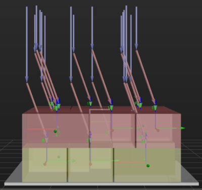
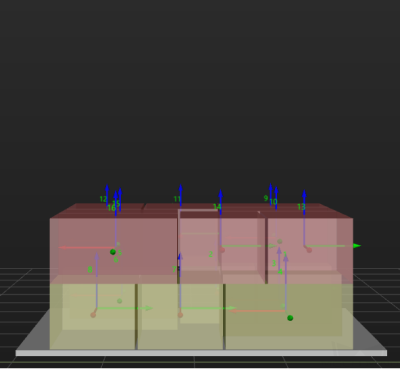
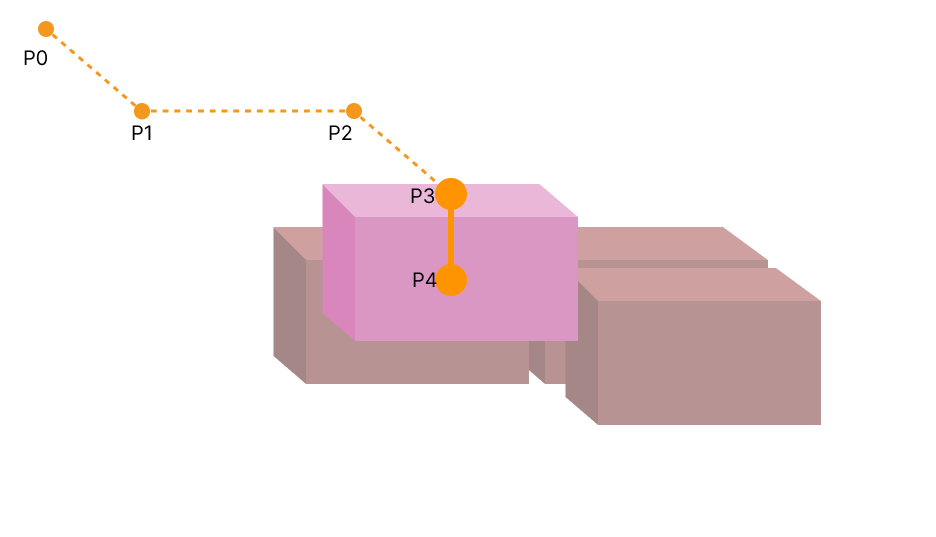
Some of the trajectories during box palletization are shown in the figure below.
|
|
|
|
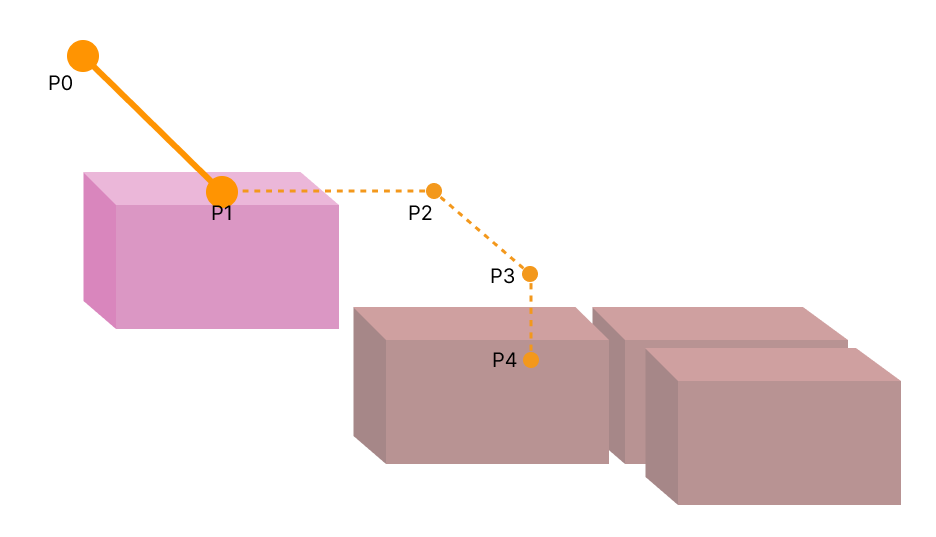
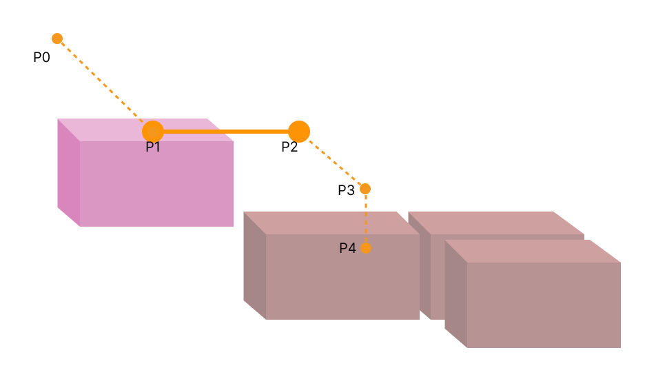
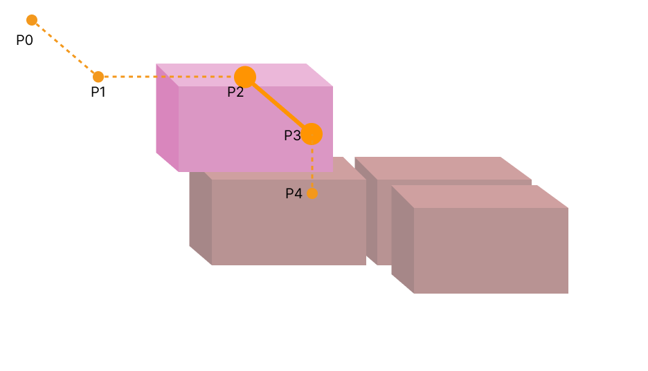
-
P0: reference point; P1: intermediate point; P2: entry point; P3: adjustment point; P4: placement point.
|
Each palletizing placement typically involves planning four points: P1, P2, P3, and P4. The reference point P0 does not require planning. |
-
P0-P1: intermediate point segment; P1-P2: entry segment; P2-P3: adjustment segment; P3-P4: placement segment.
Motion type
Joint move |
Joint motion, which guides the robot to move in a curved path. It is less likely to reach singularities in the path for joint motion.
|
Linear move |
Linear motion, which guides the robot to move linearly.
|
Singularity Avoidance
When the motion type is Linear move, enabling this function can simulate linear move by joint move with multiple segments, thus reducing singularity problems to a certain extent.
Parameter settings
| Limit to Motion Segments | Specific Number | No Limit |
|---|---|---|
Feature |
Simulate linear move using joint move with a user-specified number of segments. |
The software calculates the number of segments needed to simulate linear move. |
Advantages |
|
|
Disadvantages |
|
|
| Parameter | Description |
|---|---|
Number of Segments |
The number of joint move segments specified by the user when the Limit to Motion Segments is set to Specific Number. |
Max Position Deviation |
The maximum allowable deviation of the new multi-segment joint move path from the original linear move path. The greater the max position deviation, the higher the success rate of singularity avoidance, and the lower the similarity between the actual trajectory and the straight line. |
Max Angle Deviation |
The maximum allowable angular deviation of the new multi-segment joint move path from the original linear move path. The greater the max angle deviation, the higher the success rate of singularity avoidance, and the lower the similarity between the actual trajectory and the straight line. |
Velocity & Acceleration
Velocity and acceleration determine how fast the robot can move. Usually, the set acceleration should be lower than the velocity. When the set acceleration is higher than the velocity, the robot will move in a choppy way.
| The velocities of Vision Move and its prior and subsequent Steps should be relatively low to ensure that the objects can be picked steadily. |
Blend radius
Usually, the default setting can be used.
-
The blend radius refers to the distance between the target point and the point where the robot starts to turn. The larger the blend radius, the more smoother the robot motion transitions are. If the robot moves in a relatively small space, please set the blend radius to a smaller value.
-
If the robot moves in a relatively large space without obstacles and the distance between two consecutive path segments is long, please set the blend radius to a larger value.
Pallet Pose
This parameter specifies the pallet pose in the world reference frame.
Pallet Pattern Editor
-
Click the Pallet pattern editor button at the bottom of the panel.
-
Please refer to Pallet Pattern Editor to edit the pallet pattern.
-
After editing and saving the pallet pattern, it will take effect.