Robot Kinematics
This topic introduces the basic concepts of robot kinematics, including robot motion types, forward and inverse kinematics, handling multiple inverse solutions, and strategies for avoiding singularities. Kinematics provides the theoretical foundation for robot path planning, pose control, and vision-guided tasks.
Motion Type
Robot motion usually refers to the process of moving the robot tool center point (TCP) from point A to point B in space. The joint motion and linear motion are two fundamental methods of robot motion.
Joint Motion
Joint motion is the motion of a robot achieved by adjusting the angle or position of each joint. Each joint can rotate or move to get the entire robot tool to an expected position.
Forward and Inverse Kinematics
Forward and inverse kinematics are mutually related: joint positions are mapped to the tool pose by forward kinematics calculation, while the tool pose is mapped to the joint positions by inverse kinematic calculation.
Forward Kinematics
Forward kinematics calculates the TCP based on the known joint positions. By substituting joint positions into the robot’s configuration equations (including link lengths, joint zero positions, and rotation directions), the TCP can be uniquely determined.
When robot motion commands are sent as joint positions (JPs), the robot directly follows these JPs to move. As a result, the executed path matches the path planned in Mech-Viz exactly.
Inverse Kinematics
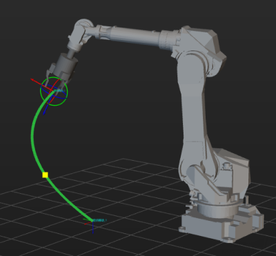
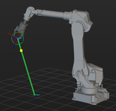
Inverse kinematics calculates joint positions based on a given TCP. Because the number of unknowns is greater than the number of knowns, inverse kinematics typically has multiple solutions, which means different joint position combinations may produce the same TCP.
![][width=500](_images/robot-basics/inverse-kinematics.png)
When tool poses are used for robot communication or motion control, the robot controller must solve inverse kinematics internally. This may lead to differences between the actual robot path and the path planned in Mech-Viz, which can result in deviations or collisions.
However, TCP-based communication is still widely used for several reasons.
-
Some robots do not support receiving joint positions in certain communication modes.
-
Robot controllers include built-in compensation algorithms, which can improve accuracy when using TCP.
-
Using TCP facilitates secondary processing in subsequent vision-guided, assembly, or calibration tasks.
Multiple Solutions and Axis Configuration
To avoid inconsistencies between the robot’s actual pose and the pose planned by Mech-Viz due to multiple solutions in inverse kinematics, some robot manufacturers provide axis configuration parameters in robot motion commands.
An axis configuration typically contains four additional parameters: three parameters constrain the angle ranges of the 1st, 4th, and 6th robot axes; one parameter defines the pose type of the 2nd and 3rd axes. By adding these boundary conditions, it can filter out unwanted solutions and ensures that the resulting robot pose matches the pose planned in Mech-Viz.
Singularity
A singularity occurs when the robot reaches a specific set of joint positions at which the kinematic equations cannot be solved or certain degrees of freedom are lost. At a singularity, motion in certain directions becomes impossible or extremely amplified, resulting in instability or unpredictable behavior.
Common Types
Based on their location and cause, robot singularities are generally classified into the following types:
-
Wrist singularity
It occurs when the three rotational axes of the wrist become collinear, causing the robot end orientation to become uncontrollable or to change abruptly. For example, in a six-axis robot, a wrist singularity may occur when the 5th axis is at 0° or 180°.
-
Elbow singularity
It occurs when the forearm and upper arm align in a straight line, making it impossible for the robot to determine an "elbow-up" or "elbow-down" configuration. This may lead to multi-solution switching or sudden motion changes during path planning.
-
Shoulder singularity
It occurs when the robot’s wrist center aligns with the axis of Joint 1, or when the joint axes form a specific collinear configuration. This causes the robot end to lose degrees of freedom in certain directions and may result in large joint rotations.
In practical industrial applications, the most common singularity occurs in six-axis spherical wrist robots when the 4th and 6th axes approach coaxial alignment during linear motion.
Singularity Avoidance
Six-axis spherical wrist robots inherently have singularities in their motion. The following strategies can help reduce the risk of encountering singularities:
-
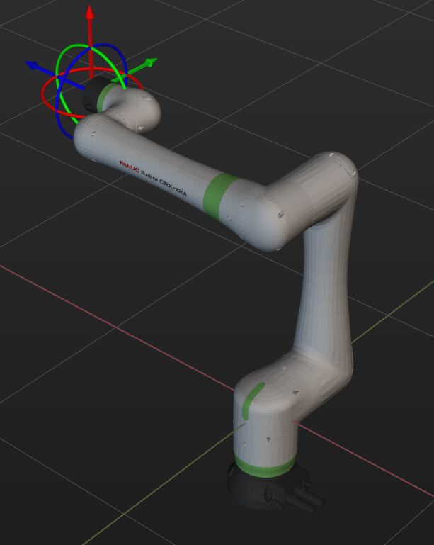
Develop offset wrist robots: Modify the robot structure to prevent coaxial alignment of the 4th and 6th axes. Examples include UR series and FANUC CRX series.
-
Optimize robot controller commands: Introduce commands that use moveJ as an approximation of moveL to improve execution feasibility.
-
Adjust software path planning: Mech-Viz reduces the robot velocity along paths where singularities may occur and attempts to plan again.
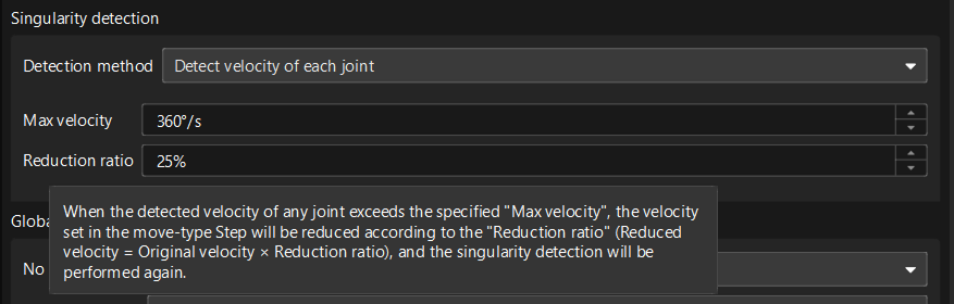
Additionally, Mech-Viz can automatically detect potential singularities during path planning. For detailed methods on singularity detection, see Singularity Detection.