3D Matching

You are currently viewing the documentation for the latest version (2.1.1). To access a different version, click the "Switch version" button located in the upper-right corner of the page.

■ If you are not sure which version of the product you are currently using, please feel free to contact Mech-Mind Technical Support.

Function

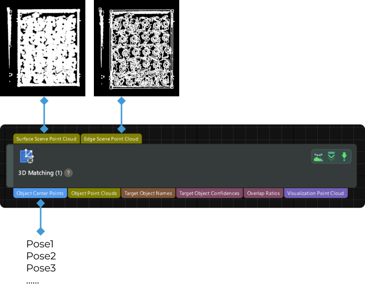
This Step matches the point cloud model of the target object with the original point cloud, removes poses of overlapped and coinciding objects, and outputs accurate poses of the target objects.

Usage Scenario

This Step is suitable for most scenarios requiring coarse and fine matching for poses of the same type of objects.

When using this Step, you can refer to “FAQs on 3D Matching” to learn how to handle common issues during 3D matching.

Input and Output

input and output

Parameters

Model Settings

Model Selection

Description: This parameter is used to select a point cloud model in the target object editor.

Instruction: Click the Target object editor button to open the target object editor. Once a configured point cloud model is saved in the target object editor, you can select it from the drop-down list below the button.

Parameter Tuning Level

Parameter Tuning Level

Description: This parameter is used to assign levels to parameters so that users with different requirements see different parameters. The following section introduces the parameters in different tuning levels.

Value list: Basic, Advanced, Expert

Default value: Basic

Click here to view the parameter description in the Basic Tuning Level

Input and Output Settings

Output Type

Description: This parameter is used to set the information type output by the Step. You can choose to output information about the pick point or the object center point.

Value list: Pick point, Object center point

  • Pick point: Output the pick point and pick point information of the target object.

  • Object center point: Output the object center point.

Default value: Pick point

Matching Mode

Auto-Set Matching Mode

Description: Once this option is enabled, the Coarse Matching Mode and Fine Matching Mode will be automatically set.

Default value: True

Coarse/Fine Matching Mode

Description: This parameter is used to set the matching model. Please set this parameter when Auto-Set Matching Mode is not selected.

Value list: Surface matching, Edge matching

  • Surface matching: Use the object’s surface point cloud model for point cloud model matching.

  • Edge matching: Use the object’s edge point cloud model for point cloud model matching.

Default value: Surface matching

Tuning recommendation: Please consider the target object features and the obtained point cloud quality when adjusting this parameter. When the surface of the object has obvious recognizable features (such as crankshafts, rotors, etc.), it is recommended to use surface matching, and you should create a point cloud model that represents the surface features of the object. When the object is relatively flat and shows clear and regular edge features under the camera (such as panels, track shoes, robot links, and brake discs), it is recommended to use edge matching, and you should create a point cloud model that represents the edge features of the object. Meanwhile, if the object point cloud quality is average, it is recommended to use surface matching.

Execution Method

Performance Mode

Description: This parameter is used to set the trade-off between accuracy and speed of matching. The higher the accuracy, the longer the time consumed.

Value list: High speed, Standard, High accuracy

Default value: Standard

Confidence Settings

Result Verification Degree

Description: This parameter is used to select the degree of strictness applied when verifying the matching results.

Value list: Low, Standard, High, Ultra-high

Default value: Standard

Tuning recommendation: In general, Standard is recommended. When it is difficult to distinguish the point cloud model from the scene point cloud, a higher result verification degree can be selected.

Confidence Threshold

Description: If the confidence of the matching result is above the threshold, the matching result is valid. The higher the confidence value is, the more accurate the matching result is.

Default value: 0.3000

Tuning recommendation: It is recommended to set this parameter to the default value and check the running result first. If false recognition occurs, it is recommended to increase this parameter; if missing recognition occurs, it is recommended to decrease this parameter.

Output

Max Outputs

Description: The parameter specifies the maximum number of output target objects for successful matches. The larger the value, the longer the Step execution time.

Default value: 10

Tuning recommendation: It is recommended to set the parameter to an appropriate value and not to set the value too large. The changes to this parameter will only take effect after re-running the Step, and the number of outputs will be limited based on the new matching result.

The actual number of output results from 3D matching may not necessarily match the set Max Outputs. If the Max Outputs is set to 5, but there are 3 recognition results in total, the final number of output recognition results is 3.

Visualization

Visualization Content

Description: After “Debug Output” is enabled, the selected option will be generated and displayed in the Debug Output window.

Value list: Output result, Confidence

Default value: Output result

Instruction: Please enable Debug Output to display poses in the Debug Output window.

Display Poses

Description: Once enabled, the pose will be displayed in the Debug Output window.

Default value: True.

Click here to view the parameter description in the Advanced Tuning Level

Input and Output Settings

Output Type

Description: This parameter is used to set the information type output by the Step. You can choose to output information about the pick point or the object center point.

Value list: Pick point, Object center point

  • Pick point: Output the pick point and pick point information of the target object.

  • Object center point: Output the object center point.

Default value: Pick point

Input Type

Description: This parameter is used to set whether to input the point cloud model.

Value list: Default, External model

  • Default: Use the point cloud model made in the target object editor for matching.

  • External model: Once this option is selected, additional input ports will be added to the Step for inputting the point cloud model and object center point of the target object. If you want to select this option, please select the “No point cloud model required” workflow in the target object editor.

Default value: Default

Matching Mode

Auto-Set Matching Mode

Description: Once this option is enabled, the Coarse Matching Mode and Fine Matching Mode will be automatically set.

Default value: True

Coarse/Fine Matching Mode

Description: This parameter is used to set the matching model. Please set this parameter when Auto-Set Matching Mode is not selected.

Value list: Surface matching, Edge matching

  • Surface matching: Use the object’s surface point cloud model for point cloud model matching.

  • Edge matching: Use the object’s edge point cloud model for point cloud model matching.

Default value: Surface matching

Tuning recommendation: Please consider the target object features and the obtained point cloud quality when adjusting this parameter. When the surface of the object has obvious recognizable features (such as crankshafts, rotors, etc.), it is recommended to use surface matching, and you should create a point cloud model that represents the surface features of the object. When the object is relatively flat and shows clear and regular edge features under the camera (such as panels, track shoes, robot links, and brake discs), it is recommended to use edge matching, and you should create a point cloud model that represents the edge features of the object. Meanwhile, if the object point cloud quality is average, it is recommended to use surface matching.

Coarse Matching Settings

Execution Method

Description: This parameter is used to set the trade-off between accuracy and speed of matching. The higher the accuracy, the longer the time consumed.

Value list: High Speed, Standard, High Accuracy, Custom

Default value: Standard

Expected Point Count of Model

Description: This parameter is used to set the expected number of points in the point cloud model. Set this parameter when Execution Method is set toCustom.

Default value: 300

Fine Matching Settings

Execution Method

Description: This parameter is used to set the trade-off between accuracy and speed of matching. The higher the accuracy, the longer the time consumed.

Value list: High speed, Standard, High accuracy, Extra high accuracy, Custom

Default value: Standard

Sampling Interval

Description: The larger the value, the fewer points in the sampled point cloud and the sparser the point cloud. As a result, the matching accuracy will be lower. However, a smaller value will lead to a longer execution time.

Default value: 5.000 mm

Max Number of Iterations

Description: The larger the value, the higher the matching accuracy and the slower the processing speed.

Default value: 40

Standard Deviation Update Step Number

Description: The parameter is used to fine-tune the standard deviation.

Default value: 3

Deviation Correction Capacity

Description: This parameter is used to set the intensity of the deviation correction to the matching result from 3D Coarse Matching. The greater the deviation correction capacity is, the more likely the coarsely matched poses can be corrected to the accurately matched poses. Please note that an excessive deviation correction capability may lead to a loss of matching accuracy.

Value list: Small, Medium, Large

Default value: Small

Extra Fine Matching

Enable Extra Fine Matching

Description: Once enabled, a different mode will be used for fine matching. For example, if the current fine matching mode is surface matching, enabling this feature will perform fine matching again using the edge point cloud model. Once enabled, the final matching accuracy may be improved, but the running time will be slightly increased.

Default value: False

Instruction: Please decide whether to enable this feature based on the actual situation. If you enable it, ensure the surface/edge point cloud model used for extra fine matching is accurate and reasonable.

Pose Filtering

Use Distance-Based NMS

Description: After this feature is enabled, candidate poses whose distances to the selected poses are less than 0.1 times the diameter of the object will be filtered out.

Default value: True

Auto-Set Max Model Rotation Angle

Description: Once enabled, the Max Model Rotation Angle will be automatically set. This feature is mainly used for filtering the poses that are wrongly matched with the front or back sides of the target object.

Default value: True

Max Model Rotation Angle

Description: When the point cloud model matches with the scene point cloud, the poses will be filtered by the point cloud model’s rotation angle about its X-axis or Y-axis. When the model’s rotation angle exceeds the Max Model Rotation Angle, the pose will be filtered out.

Default value: 135.00°

Adjust or Filter Poses from Coarse Matching

Select Strategy

Description: When Adjust X-axis orientation is selected, the Z-axes of the poses obtained from coarse matching remain fixed, while the X-axes rotate to the specified direction. When Filter potentially false matches is selected, poses that could cause matching failures—calculated in the target object editor—are used to refine the matching process, filtering out unreliable poses from coarse matching.

Value list: None, Adjust X-axis orientation, Filter potentially false matches

Option Description Tuning Examples

N/A

Disable the "Adjust or Filter Poses from Coarse Matching" feature.

Adjust X-axis orientation

Adjust X-axis orientation: Fix the Z-axis of the pose obtained from coarse matching and rotate the X-axis to the specified direction. This parameter is typically used for circularly symmetric target objects (e.g., rings, brake discs) to ensure that the X-axis of the target object poses point in the same direction.

adjust x axis orientation effect

Filter potentially false matches

Uses results calculated in the target object editor to assist matching, helping to filter the coarsely matched poses. This parameter is typically used for symmetric or nearly symmetric target objects (e.g., track links) to filter out potentially incorrect poses from multiple candidate poses.

  • For rectangular target objects with 180-degree rotational symmetry, to ensure that the X-axis orientations of the matched poses match those of the point cloud model, you can select “Filter potentially false matches.” The adjustment result is shown in the figure below.

    filter potentially false matches 1

  • If a target object is approximately 180° symmetrical, but the two ends of the target object have different structures, the target object is considered not symmetrical. Such target objects are prone to incorrect recognition. To improve the recognition accuracy, it is recommended to select “Filter potentially false matches” for this type of target objects. The adjustment result is shown in the figure below.

    filter potentially false matches 2

Default value: None

Instruction: If you need to use the Filter potentially false matches parameter, please enable the Configure point cloud model under Point cloud model settings in the target object editor. Then, select Calculate poses to filter matching result or Configure symmetry manually and configure the relevant settings as needed.

Augment Long Thin Objects

Enable Augmentation for Long Thin Objects

Description: When matching long and thin target objects (such as shafts and square tubes) with aspect ratios greater than 3:1, the target object and point cloud are prone to misalignment along the long axis of the object, with the ends unable to align accurately. Enabling this feature can improve the matching accuracy of long and thin target objects.

Default value: True

Confidence Settings

To ensure that the target objects on the top layer that are normally placed can be accurately recognized, you need to set the confidence.

Result Verification Degree

Description: This parameter is used to select the degree of strictness applied when verifying the matching results.

Value list: Low, Standard, High, Ultra-high, Custom

Default value: Standard

Tuning recommendation: In general, “Standard” is recommended. When it is difficult to distinguish the point cloud model from the scene point cloud, a higher result verification degree can be selected.

Search Radius

Description: The smaller the search radius, the lower the matching result validation score; the larger the search radius, the higher the matching result validation score. You need to set this parameter when Result Verification Degree is set toCustom.

Default value: 10.000 mm

Tuning recommendation: If the matching result validation score is low, you can appropriately increase this parameter; if the matching result validation score is high, you can appropriately decrease this parameter.

Sampling Interval

Description: This parameter is used for the downsampling of the model and scene point cloud (only for verifying the matching results). The greater the value, the fewer points in the downsampled point clouds. You need to set this parameter when Result Verification Degree is set toCustom.

Default value: 5.000 mm

Confidence Threshold

Description: If the confidence of the matching result is above the threshold, the matching result is valid. The higher the confidence value is, the more accurate the matching result is.

Default value: 0.3000

Tuning recommendation: It is recommended to set this parameter to the default value and check the running result first. If false recognition occurs, it is recommended to increase this parameter; if missing recognition occurs, it is recommended to decrease this parameter.

Consider Normal Deviation in Surface Matching

Description: When verifying the surface matching results, consider the angle deviations between the normals of the points in the scene point cloud and their counterparts in the point cloud model. Once this parameter is selected, the number of output matching results will be fewer, but the accuracy of the matching results will be enhanced.

Default value: Unselected

Confidence Strategy

Description: This parameter is used to select the method to set the joint scoring strategy.

Value list: Auto, Manual

  • Auto: Set the joint scoring strategy automatically.

  • Manual: Set the joint scoring strategy manually.

Default value: Auto

Joint Scoring Strategy

Description: This parameter is used to select the scoring strategy used for verification. When “Consider both surface and edge” is selected, the parameters for surface matching and edge matching under Confidence Settings need to be set separately for better filtering of matching results.

Value list: Consider both surface and edge, Consider surface only

Default setting: Consider surface only

Instruction: When the “Joint Scoring Strategy” is set to “Consider both surface and edge,” it is recommended to set the value of “Surface Matching Confidence Threshold” higher than that of “Edge Matching Confidence Threshold.” When the “Joint Scoring Strategy” is set to “Consider surface only,” only the surface matching score will be used for matching result verification.

Model Processing

Consider Holes in Surface Matching

Description: During surface matching, if the outer contours of the point cloud model and the point cloud of the target object match, but either the point cloud of the target object or the point cloud model has holes, it can lead to mismatches (such as mismatches between rings and disks). Once this option is enabled, if the surface point cloud model and the target object cannot match in the holes, the corresponding surface matching confidence decreases. If the surface point cloud model has been edited and no longer accurately reflects the shape of the actual object, for example, if complex patterns in the center of the point cloud model have been deleted, it is recommended to disable this feature.

Default value: True

Remove Coinciding Poses

Remove Poses of Coinciding Objects

Description: This parameter is used to determine whether to enable the feature of removing coinciding objects.

Default value: True

Coincidence Ratio Threshold

Description: If the coincidence ratio of the masks, obtained by orthographically projecting the two object point clouds, exceeds this value, the pose with lower confidence will be removed. Please set this parameter when Remove Poses of Coinciding Objects is enabled.

Default value: 30%

Remove Overlapped Poses

Remove Poses of Overlapped Objects

Description: This parameter is used to determine whether to enable the feature of removing overlapped objects.

Default value: True

Overlap Ratio Threshold

Description: The threshold of the overlap ratio between the object and other objects. If the overlap ratio is above this value, the object will be considered overlapped. Please set this parameter when Remove Poses of Overlapped Objects is enabled.

Overlap Ratio = Projected Area of the Point Cloud Overlapping the Object / Projected Area of the Object Point Cloud Model

Default value: 30%

Output

Max Outputs

Description: The parameter specifies the maximum number of output target objects for successful matches. The larger the value, the longer the Step execution time.

Default value: 10

Tuning recommendation: It is recommended to set the parameter to an appropriate value and not to set the value too large. The changes to this parameter will only take effect after re-running the Step, and the number of outputs will be limited based on the new matching result.

The actual number of output results from 3D matching may not necessarily match the set Max Outputs. If the Max Outputs is set to 5, but there are 3 recognition results in total, the final number of output recognition results is 3.

Visualization

Visualization Content

Description: After “Debug Output” is enabled, the selected option will be generated and displayed in the Debug Output window.

Value list: Coarse matching, Fine matching, Adjust X-axis orientation, Confidence, Remove overlapped poses, Output result

Default value: Output result

Instruction: Please enable Debug Output to display poses in the Debug Output window.

Display Poses

Description: Once enabled, the pose will be displayed in the Debug Output window.

Default value: True.

Click here to view the parameter description in the Expert Tuning Level
Output Type

Description: This parameter is used to set the information type output by the Step. You can choose to output information about the pick point or the object center point.

Value list: Pick point, Object center point

  • Pick point: Output information about pick points.

  • Object center point: Output information about the object center point.

Default value: Pick point

Input Type

Description: This parameter is used to set whether to input the point cloud model.

Value list: Default, External model

  • Default: Use the point cloud model made in the target object editor for matching.

  • External model: Once this option is selected, additional input ports will be added to the Step for inputting the point cloud model and object center point of the target object. If you want to select this option, please select the “No point cloud model required” workflow in the target object editor.

Default value: Default

Point Cloud Preprocessing

Use Downsampling

Description: Once enabled, the point cloud will be downsampled.

Default value: False

Sampling Interval

Description: The larger the value, the fewer points in the sampled point cloud and the sparser the point cloud. As a result, the matching accuracy will be lower. However, a smaller value will lead to a longer execution time. You need to set this parameter after enabling Downsampling.

Default value: 3.000 mm

Matching Mode

Auto-Set Matching Mode

Description: Once this option is enabled, the Coarse Matching Mode and Fine Matching Mode will be automatically set.

Default value: True

Coarse/Fine Matching Mode

Description: This parameter is used to set the matching model. Please set this parameter when Auto-Set Matching Mode is not selected.

Value list: Surface matching, Edge matching

  • Surface matching: Use the object’s surface point cloud model for point cloud model matching.

  • Edge matching: Use the object’s edge point cloud model for point cloud model matching.

Default value: Surface matching

Tuning recommendation: Please consider the target object features and the obtained point cloud quality when adjusting this parameter. When the surface of the object has obvious recognizable features (such as crankshafts, rotors, etc.), it is recommended to use surface matching, and you should create a point cloud model that represents the surface features of the object. When the object is relatively flat and shows clear and regular edge features under the camera (such as panels, track shoes, robot links, and brake discs), it is recommended to use edge matching, and you should create a point cloud model that represents the edge features of the object. Meanwhile, if the object point cloud quality is average, it is recommended to use surface matching.

Coarse Matching Settings

Execution Method

Description: This parameter is used to set the trade-off between accuracy and speed of matching. The higher the accuracy, the longer the time consumed.

Value list: High Speed, Standard, High Accuracy, Custom

Default value: Standard

Expected Point Count of Model

Description: This parameter is used to set the expected number of points in the point cloud model. Set this parameter when Execution Method is set toCustom.

Default value: 300

Auto Set Max Outputs per Point Cloud

Description: Enable to set the maximum number of output results for a single point cloud automatically.

Default value: True

Max Point Cloud of Sampled Scene Point Cloud

Description: If the number of points of the sampled scene point cloud is larger than this value, the scene point cloud will be ignored and empty data will be output.

Default value: 1000000

Voting Settings

Auto-Set Voting Parameters

Description: Enable to automatically configure all other parameters under the “Voting Settings” parameter group.

Default value: True

Upper Limit of Point Pair Count per Feature

Description: This parameter specifies the maximum number of point pairs contained in each feature during the model analysis. The smaller this value is, the faster the processing speed, but the lower the accuracy.

Default value: 1000

Distance Quantification

Description: The parameter for the quantification of the distance between points (Distance between Two Points=Distance Quantification*Sampling Interval). The larger the value is, the less accurate the matching results.

Default value: 2.0000

Angle Quantification

Description: The parameter for the quantification of the angle between the normals of the points in the point pair (Angle between Two Vectors = 360°/Angle Quantification). The larger this value is, the more accurate the matching results, but it also requires higher point cloud quality.

Default value: 30

Vote Ratio Lower Threshold

Description: In the matching process, each object pose will earn a score. When the pose score is higher than the product of the highest score in the vote and Vote Ratio Lower Threshold, the corresponding pose will be involved in the pose verification. The lower this value is, the more likely an exact match will be found, but the execution time will also be longer.

Default value: 80%

Referring Point Sampling Step

Description: This parameter is used to adjust the step size to downsample the scene point cloud and obtain referring points that form point pairs with the referred points. When the value is larger, the execution speed is faster, but the matching accuracy is reduced.

Default value: 5

Referred Point Sampling Step

Description: This parameter is used to adjust the step size to downsample the scene point cloud and obtain referred points that form point pairs with the referring points. When the value is larger, the execution speed is faster, but the matching accuracy is reduced.

Default value: 1

Pose Verification Settings

Voxel Length Generation Strategy

Description: Select the method to generate the voxel length.

Value list: Auto, Manual

Default value: Auto

Tuning recommendation: Auto is recommended for new users.

Voxel Length

Description: This parameter is used to set the length of the voxel. The larger the value, the less accurate the matching results.

Default value: 3.0 mm

Min Voxel Length

Description: This parameter is used to set the minimum voxel length.

Default value: 0.100 mm

Max Voxel Length

Description: This parameter is used to set the maximum voxel length.

Default value: 15.000 mm

Fine Matching Settings

Execution Method

Description: This parameter is used to set the trade-off between accuracy and speed of matching. The higher the accuracy, the longer the time consumed.

Value list: High speed, Standard, High accuracy, Extra high accuracy, Custom

Default value: Standard

Sampling Interval

Description: The larger the value, the fewer points in the sampled point cloud and the sparser the point cloud. As a result, the matching accuracy will be lower. However, a smaller value will lead to a longer execution time.

Default value: 5.000 mm

Max Number of Iterations

Description: The larger the value, the higher the matching accuracy and the slower the processing speed.

Default value: 40

Standard Deviation Update Step Number

Description: The parameter is used to fine-tune the standard deviation.

Default value: 3

Deviation Correction Capacity

Description: This parameter is used to set the intensity of the deviation correction to the matching result from 3D Coarse Matching. The greater the deviation correction capacity is, the more likely the coarsely matched poses can be corrected to the accurately matched poses. Please note that an excessive deviation correction capability may lead to a loss of matching accuracy.

Value list: Small, Medium, Large

Default value: Small

Auto Set Max Outputs per Point Cloud

Description: Enable to set the maximum number of output results for a single point cloud automatically.

Default value: True

Max Outputs per Point Cloud

Description: This parameter is used to set the maximum number of output results for a single point cloud. If a single point cloud has multiple matching results, the results will be sorted in descending order according to the scores, and then the results with higher scores will be output according to the upper limit. Please set this parameter when Auto-Set Max Outputs per Point Cloud is disabled.

Default value: 1

Extra Fine Matching

Enable Extra Fine Matching

Description: Once enabled, a different mode will be used for fine matching. For example, if the current fine matching mode is surface matching, enabling this feature will perform fine matching again using the edge point cloud model. Once enabled, the final matching accuracy may be improved, but the running time will be slightly increased.

Default value: False

Instruction: Please decide whether to enable this feature based on the actual situation. If you enable it, ensure the surface/edge point cloud model used for extra fine matching is accurate and reasonable.

Pose Filtering

Use Distance-Based NMS

Description: After this feature is enabled, candidate poses whose distances to the selected poses are less than 0.1 times the diameter of the object will be filtered out.

Default value: True

Auto-Set Max Model Rotation Angle

Description: Once enabled, the Max Model Rotation Angle will be automatically set. This feature is mainly used for filtering the poses that are wrongly matched with the front or back sides of the target object.

Default value: True

Adjust or Filter Poses from Coarse Matching

Select Strategy

Description: When Adjust X-axis orientation is selected, the Z-axes of the poses obtained from coarse matching remain fixed, while the X-axes rotate to the specified direction. When Filter potentially false matches is selected, poses that could cause matching failures—calculated in the target object editor—are used to refine the matching process, filtering out unreliable poses from coarse matching.

Value list: None, Adjust X-axis orientation, Filter potentially false matches

Option Description Tuning Examples

N/A

Disable the "Adjust or Filter Poses from Coarse Matching" feature.

Adjust X-axis orientation

Adjust X-axis orientation: Fix the Z-axis of the pose obtained from coarse matching and rotate the X-axis to the specified direction. This parameter is typically used for circularly symmetric target objects (e.g., rings, brake discs) to ensure that the X-axis of the target object poses point in the same direction.

adjust x axis orientation effect

Filter potentially false matches

Uses results calculated in the target object editor to assist matching, helping to filter the coarsely matched poses. This parameter is typically used for symmetric or nearly symmetric target objects (e.g., track links) to filter out potentially incorrect poses from multiple candidate poses.

  • For rectangular target objects with 180-degree rotational symmetry, to ensure that the X-axis orientations of the matched poses match those of the point cloud model, you can select “Filter potentially false matches.” The adjustment result is shown in the figure below.

    filter potentially false matches 1

  • If a target object is approximately 180° symmetrical, but the two ends of the target object have different structures, the target object is considered not symmetrical. Such target objects are prone to incorrect recognition. To improve the recognition accuracy, it is recommended to select “Filter potentially false matches” for this type of target objects. The adjustment result is shown in the figure below.

    filter potentially false matches 2

Default value: None

Instruction: If you need to use the Filter potentially false matches parameter, please enable the Configure point cloud model under Point cloud model settings in the target object editor. Then, select Calculate poses to filter matching result or Configure symmetry manually and configure the relevant settings as needed.

Augment Long Thin Objects

Enable Augmentation for Long Thin Objects

Description: When matching long and thin target objects (such as shafts and square tubes) with aspect ratios greater than 3:1, the target object and point cloud are prone to misalignment along the long axis of the object, with the ends unable to align accurately. Enabling this feature can improve the matching accuracy of long and thin target objects.

Default value: True

Aspect Ratio Threshold

Description: When the ratio of the long and short sides of the target object is less than this parameter value, the target object will not be recognized as a long and thin object, and the augmentation algorithm for long and thin objects will not take effect.

Default value: 3.0000

Step Ratio

Description: This parameter specifies the step for translation attempts of the target object point cloud during matching. Step = object length × step ratio.

Default value: 5.00%

Number of Steps

Description: This parameter specifies the number of steps for translation attempts of the target object point cloud during matching. The target object point cloud will be translated along the positive and negative directions of the object’s long axis. Thus, the total number of attempts = 2 × number of steps.

Default value: 5

Confidence Settings

To ensure that the target objects on the top layer that are normally placed can be accurately recognized, you need to set the confidence.

Result Verification Degree

Description: This parameter is used to select the degree of strictness applied when verifying the matching results.

Value list: Low, Standard, High, Ultra-high, Custom

Default value: Standard

Tuning recommendation: In general, “Standard” is recommended. When it is difficult to distinguish the point cloud model from the scene point cloud, a higher result verification degree can be selected.

Search Radius

Description: When the distance between the scene point cloud and the point cloud model is less than this value, it is considered that the scene point cloud and point cloud model coincide. The more points that coincide, the higher the verification score for the matching result. You need to set this parameter when Result Verification Degree is set toCustom.

Default value: 10.000 mm

Sampling Interval

Description: This parameter is used for the downsampling of the model and scene point cloud (only for verifying the matching results). The greater the value, the fewer points in the downsampled point clouds. You need to set this parameter when Result Verification Degree is set toCustom.

Default value: 5.000 mm

Confidence Threshold

Description: If the confidence of the matching result is above the threshold, the matching result is valid. The higher the confidence value is, the more accurate the matching result is.

Default value: 0.3000

Tuning recommendation: It is recommended to set this parameter to the default value and check the running result first. If false recognition occurs, it is recommended to increase this parameter; if missing recognition occurs, it is recommended to decrease this parameter.

Consider Normal Deviation in Surface Matching

Description: When verifying the surface matching results, consider the angle deviations between the normals of the points in the scene point cloud and their counterparts in the point cloud model. Once this parameter is selected, the number of output matching results will be fewer, but the accuracy of the matching results will be enhanced.

Default value: Unselected

Confidence Strategy

Description: This parameter is used to select the method to set the joint scoring strategy.

Value list: Auto, Manual

  • Auto: Set the joint scoring strategy automatically.

  • Manual: Set the joint scoring strategy manually.

Default value: Auto

Joint Scoring Strategy

Description: This parameter is used to select the scoring strategy used for verification. When “Consider both surface and edge” is selected, the parameters for surface matching and edge matching under Confidence Settings need to be set separately for better filtering of matching results.

Value list: Consider both surface and edge, Consider surface only

Default setting: Consider surface only

Instruction: When the “Joint Scoring Strategy” is set to “Consider both surface and edge,” it is recommended to set the value of “Surface Matching Confidence Threshold” higher than that of “Edge Matching Confidence Threshold.” When the “Joint Scoring Strategy” is set to “Consider surface only,” only the surface matching score will be used for matching result verification.

Model Processing

Consider Holes in Surface Matching

Description: During surface matching, if the outer contours of the point cloud model and the point cloud of the target object match, but either the point cloud of the target object or the point cloud model has holes, it can lead to mismatches (such as mismatches between rings and disks). Once this option is enabled, if the surface point cloud model and the target object cannot match in the holes, the corresponding surface matching confidence decreases. If the surface point cloud model has been edited and no longer accurately reflects the shape of the actual object, for example, if complex patterns in the center of the point cloud model have been deleted, it is recommended to disable this feature.

Default value: True

Remove Coinciding Poses

Remove Poses of Coinciding Objects

Description: This parameter is used to determine whether to enable the feature of removing coinciding objects.

Default value: True

Coincidence Ratio Threshold

Description: If the coincidence ratio of the masks, obtained by orthographically projecting the two object point clouds, exceeds this value, the pose with lower confidence will be removed. Please set this parameter when Remove Poses of Coinciding Objects is enabled.

Default value: 30%

Method to Generate Pixel Size

Description: When the coincidence ratio is calculated based on the 2D orthographic projection of the object point cloud, select the method to generate the size per pixel on the projected 2D image.

Value list: Auto, Manual

  • Auto: Automatically generate the size per pixel on the projected 2D image.

  • Manual: Set the Pixel Size manually.

Default value: Auto

Pixel Size

Description: The size per pixel on the projected 2D image when the coincidence ratio is calculated based on the 2D orthographic projection of the object point cloud. It is recommended to set the Pixel Size the same as the Sampling Interval when making the point cloud model. If the value is set too large, the accuracy of the calculated coincidence ratio may be reduced. If the value is set too small, the calculated coincidence ratio may be lower. When Method to Generate Pixel Size is set to Manual, please set this parameter.

Default value: 2.500 mm

Remove Overlapped Poses

Remove Poses of Overlapped Objects

Description: This parameter is used to determine whether to enable the feature of removing overlapped objects.

Default value: True

Overlap Ratio Threshold

Description: The threshold of the overlap ratio between the object and other objects. If the overlap ratio is above this value, the object will be considered overlapped. Please set this parameter when Remove Poses of Overlapped Objects is enabled.

Overlap Ratio = Projected Area of the Point Cloud Overlapping the Object / Projected Area of the Object Point Cloud Model

Default value: 30%

Method to Generate Pixel Size

Description: When the overlap ratio is calculated based on the 2D orthographic projection of the object point cloud, select the method to generate the size per pixel on the projected 2D image.

Value list: Auto, Manual

  • Auto: Automatically generate the size per pixel on the projected 2D image.

  • Manual: Set the Pixel Size manually.

Default value: Auto

Pixel Size

Description: The size per pixel on the projected 2D image when the overlap ratio is calculated based on the 2D orthographic projection of the object point cloud. It is recommended to set the “Pixel Size” the same as the “Sampling Interval” when making the point cloud model. If the value is set too large, the accuracy of the calculated overlap ratio may be reduced. If the value is set too small, the calculated overlap ratio may be lower. When Method to Generate Pixel Size is set to Manual, please set this parameter.

Default value: 2.500 mm

Range of Scene Point Removal around Object

Description: Within this range, points in the scene point cloud around the object will be removed, and the rest scene point cloud will be involved in the overlap detection.

Default value: 3.000 mm

Output

Max Outputs

Description: The parameter specifies the maximum number of output target objects for successful matches. The larger the value, the longer the Step execution time.

Default value: 10

Tuning recommendation: It is recommended to set the parameter to an appropriate value and not to set the value too large. The changes to this parameter will only take effect after re-running the Step, and the number of outputs will be limited based on the new matching result.

The actual number of output results from 3D matching may not necessarily match the set Max Outputs. If the Max Outputs is set to 5, but there are 3 recognition results in total, the final number of output recognition results is 3.

Visualization

Visualization Content

Description: After “Debug Output” is enabled, the selected option will be generated and displayed in the Debug Output window.

Value list: Coarse matching, Fine matching, Coarse matching pose verification (Need to re-run Step), Fine matching pose verification, Adjust X-axis orientation, Confidence, Remove coinciding poses, Remove overlapped poses, Count limit, and Output result

Default value: Output result

Instruction: Please enable Debug Output to display poses in the Debug Output window.

Display Poses

Description: Once enabled, the pose will be displayed in the Debug Output window.

Default value: True.

Pose Type

Description: This parameter is used to select the type of poses displayed in the visualization interface. Once Auto is selected, the pose type will be the same as the set “Output Type.”

Value list: Auto, Object center point, Pick point

Default value: Auto

Is this page helpful?

You can give a feedback in any of the following ways:

We Value Your Privacy

We use cookies to provide you with the best possible experience on our website. By continuing to use the site, you acknowledge that you agree to the use of cookies. If you decline, a single cookie will be used to ensure you're not tracked or remembered when you visit this website.