Configure the Production Interface
This chapter is intended to guide the engineer through configuring the production interface. You can click the Setting button on the right side of the toolbar to open the Production Interface Configurator.
|
The production interface cannot be configured if the solution has not been saved to a directory. See Save the Solution to learn about saving methods. |
Configuration Process
You should configure the content for display and define the functions you intend to use before applying the production interface. The overall configuration process is shown in the figure below.

-
Basic info: for configuring the solution name, production unit name, and unit function.
-
Running views: for selecting the associated project and specifying the content to be displayed in the running views.
-
New target object: for selecting the method to make the point cloud model for the new target object and setting the production recipe when there are new infeed target objects.
The production recipe is the parameter recipe used in the dedicated project and is the important basis for switching and adding target object types.
-
General settings: for saving production data, setting up role-based access control, and creating the document.
-
Custom settings: for customizing alert rules, monitoring the disk space, etc.
Basic Info
Basic info contains the solution name, production unit name, and unit function. Please follow the steps below to configure.
-
Configure the solution name.
The solution name will be displayed as the title on the production interface. This setting will not affect the name of the actual solution file (.msol).
-
Configure the production unit.
-
Name the production unit.
A production unit is the minimum running unit on the production interface. A maximum of 10 production units can be added for a production interface. Click the + button to add a production unit. Click - to delete the last added production unit.
-
Select the Unit Function.
The functions of the production unit are categorized into Display running views and Display running views & Add new target object.
-
Display running views: provide the functions of displaying running views and switching target objects.
-
Display running views & Add new target object: provide the functions of displaying running views, switching target objects, and adding new target objects. The functionality of “adding new target objects” depends on the parameter recipes that are utilized within the project.
If no parameter recipe is applied in any one of the projects in the solution, the Display running views & Add new target object function cannot be selected.
-
-
|
Click the Save button to save the configured content, and you can continue to configure the next time you open the Production Interface Configurator. The production interface cannot be started until all configurations have been completed in the Production Interface Configurator. |
After completing the solution name and production unit configuration, click Next and you can start to configure the running views.
Running Views
In the Running views page, select a project to associate and configure the content to be displayed in the production unit. Please follow the steps below to configure.
-
Select the project to associate.
The associated project determines which views of the production unit can be displayed and the ways to switch or add target object types. It is recommended to select the main recognition project under the solution.
The projects that can be associated depend on the selected Unit function. If the unit function is Display running views & Add new target object, only projects containing one or more parameter recipes can be associated.
-
Set view content.
-
Select running views.
The running views are used to display the production status. This visualization area can display four different running views for various purposes: Station live, Recognition result, Deep learning result, and Picking sequence. The “Station live” is the default option. You can click the + button to add other running views. Click - to delete the last added running view.
-
For running views of the same type, you can add duplicates, but a maximum of four running views are supported.
-
At least one running view should be kept.
-
-
Set the display name.
When setting a display name for the running view, ensure that the name does not duplicate the names of any previously added running views.
-
Select Step.
After selecting the running view(s), you should select the Step corresponding to each view and click the Preview button to view the content. The supported Steps for each running view are listed in the table below.
Running view option Added by default Setting procedures Selectable Step Station live
Yes
① Select method to capture images. ②Select a Step as the source of the view.
Use multiple cameras and stitch captured images: Merge Point Clouds.
Use one camera to capture images: Camera 2D, Capture Images from Camera, Read Images V2.
Recognition result
No
Select a Step as the source of the view.
3D Target Object Recognition, 3D Matching, 3D Fine Matching Lite, 3D Matching and Classification (Multiple Models).
Deep learning result
No
Select a Step as the source of the view.
Deep Learning Model Package Inference.
Picking sequence (custom)
No
① Set the point cloud source. ②Select a Step as the source of the view. ③ Preview the picking sequence.
Use Steps that output scene point clouds in the robot reference frame as the point cloud source, or customize the point cloud source. For the pose source, use Steps with an output port type of “PoseList,” excluding “3D Target Object Recognition” and “3D Matching”.
2D image visualization
No
Select a Step as the source of the view.
Display 2D images and measurement results. In a project, the Image Visualization (2D) Step is typically used to integrate image data with measurement results for visualization, and to display them on the production interface.
-
Please select the running views related to the project. For example, if you add “Deep learning result” running view when the associated project lacks deep learning-related Steps, no content can be displayed in this running view, and you cannot proceed with the configuration.
-
If the output ports of the “3D Target Object Recognition” or “3D Matching” Step change, please re-select the Step in Running views section.
-
-
Now you have finished configuring the running views. Click Next to add new target objects.
New Target Object
Different unit functions (Display running views and Display running views & Add new target object) set in the Basic info page will lead to different content in the New target object page.
Display Running Views
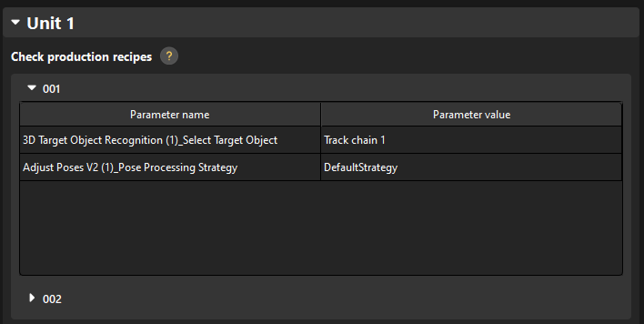
If the unit function is set to Display running views, only production recipes will be displayed in this page for basic target object switching, as shown in the figure below.
Display Running Views & Add New Target Object
If the unit function is set to Display running views & Add new target object, production recipes used for basic target object switching will be displayed in this page. You should also set the method to add new target objects.
-
Select the method to make target object model.
Four methods to make the point cloud model for the new type of target objects are listed in the table below:
No. Make point cloud model by Description Further operation 1
STL model
Make the point cloud model by importing the STL model.
-
2
Common 3D shape
Create a common 3D shape as the point cloud model.
Select a common 3D shape that can represent the target object.
3
Model-making project
Use a separate vision project to generate the point cloud model file.
You should select a vision project that can generate point cloud model of the target object.
4
Target object editor
Use the target object editor to make the point cloud model for the target object.
-
-
Set production recipe.
Set the way to input the production recipe parameters. The following ways are supported:
-
User input: The corresponding parameter value is a variable. You cannot specify a value here but can set the value each time you add a new target object in the production interface.
-
System default: The corresponding parameter value is a constant. You can select an option in the Parameter value column.
-
Now you have finished configuring the settings related to new target objects. Click Next to proceed with the general settings.
General Settings
-
Production data storage.
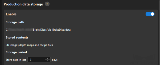
To save the production data, enable the Production data storage feature, set the following parameters, and the production data will be saved to the specified path.
Parameter Description Storage period
This parameter specifies the number of days the project has been actually running. Data generated within this period will be retained.
Storage mode
-
Save all: All data will be saved.
-
Save upon Error: Only data generated when exceptions occur during production will be saved.
The data of software exceptions will be saved in either of the two modes. Creating subfolder by
You can choose whether to create subfolders based on the recipe according to your actual needs.
-
Production data will be saved by default to the path set by the Data Storage feature in the Project Assistant.
-
Only image data captured by the “Capture Images from Camera” Step with the “Camera Type” set to “Mech-Eye” can be saved. Currently, saving image data captured by cameras of other types is not supported.
-
-
Set the start interface for the software.
-
Select the default interface to enter.
Select the default interface to enter when the software is restarted. This setting takes effect only if the solution is already auto-loaded.
-
Select the default display mode for the running view.
Choose between “Single-window” and “Multi-window” as the default display mode for the running view.
-
Determine whether to automatically switch production units when the project is running.
If you select “Enable,” you will need to set a time interval, which represents the minimum time between consecutive automatic switches of production units.
-
-
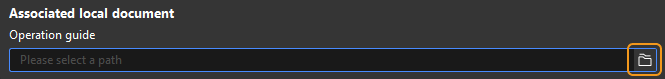
Document generator.
-
Click the folder icon under “Associated local document” to select the PDF file. Then you can open the operation guide by clicking the Document icon directly on the production interface.
-
Now you have finished configuring the general settings. Click Next to proceed with the custom settings.
Custom Settings
The custom settings include Disk space monitoring and Brand display. Please follow the steps below to configure.
-
Disk space monitoring
Add rules to monitor the free space of disks. Insufficient free disk space will affect the normal running of the system.
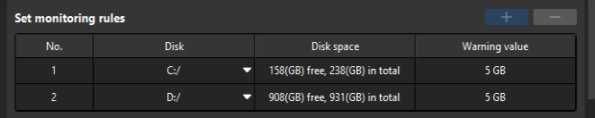
Click + or - to add or delete a monitoring rule.
-
Only the system disk(s) will be monitored by default.
-
Up to two disks can be monitored.
-
-
Brand display
Display the brand and product information you select.
The Mech-Mind brand logo will be displayed by default.
After completing the Custom settings, you have finished all configurations of the production interface. Then you can use the production interface in real production.