Configure Collision Detection
In this functional panel, you can configure the collision detection. During robot path planning, Mech-Viz will highlight areas where collisions might occur in the 3D simulation area and halt the project to prevent actual collisions.
Please refer to Topic: Collision Detection for more know-how on parameter adjustment and troubleshooting.
Check Collision Detection Configuration
This table dynamically displays the configuration of all types of collision detection. Click Legend to view what the different colors in the table represent. Hover the mouse cursor over the specific cell to check how to enable the corresponding collision detection.
Point Cloud Collision Detection
When the number, position, shape, or dimensions of the objects that should be involved in collision detection cannot be determined, and therefore they cannot be added as scene objects in advance, visual recognition should be used. In this situation, point cloud collision detection needs to be enabled.
The more items involved in point cloud collision detection, the lower the collision risk in the robot’s motion path, but the time required for path planning will also increase accordingly.
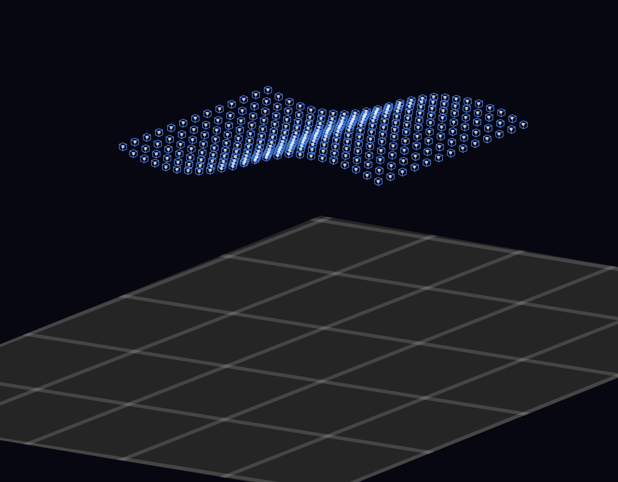
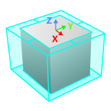
Point Cloud Form for Collision Detection
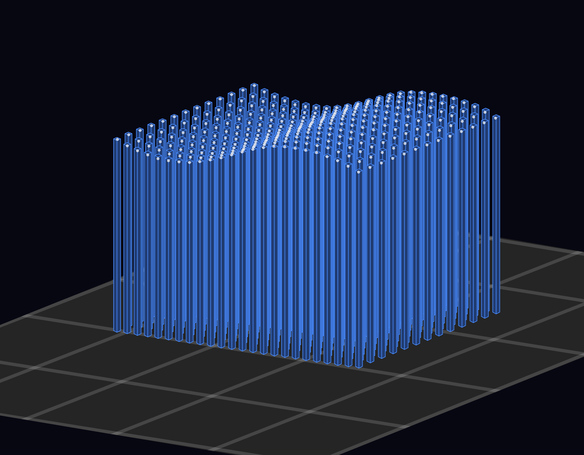
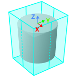
| Point cloud cube | Point cloud column |
|---|---|
Fill the surface of the point cloud with cubes for collision detection calculations. |
The space beneath the point cloud will be filled with columns along the negative direction of the Z-axis of the world reference frame for collision detection calculations. The extension length of the point cloud columns in the world reference frame can be determined by setting the Column base position. |
|
|
| When the model of the robot tool is in STL format, Point cloud column is recommended. Please refer to Tool Model for a detailed explanation. |
In depalletizing scenario, using a point cloud column can avoid collisions with other cartons when using vacuum grippers to pick cartons, especially when the vacuum gripper suctions the carton from the side surface.
| Tool collides with carton | Collision not detected with point cloud cube | Collision detected with point cloud column |
|---|---|---|
|
|
|

Point Cloud Form for Collision Detection |
Suitable scenario |
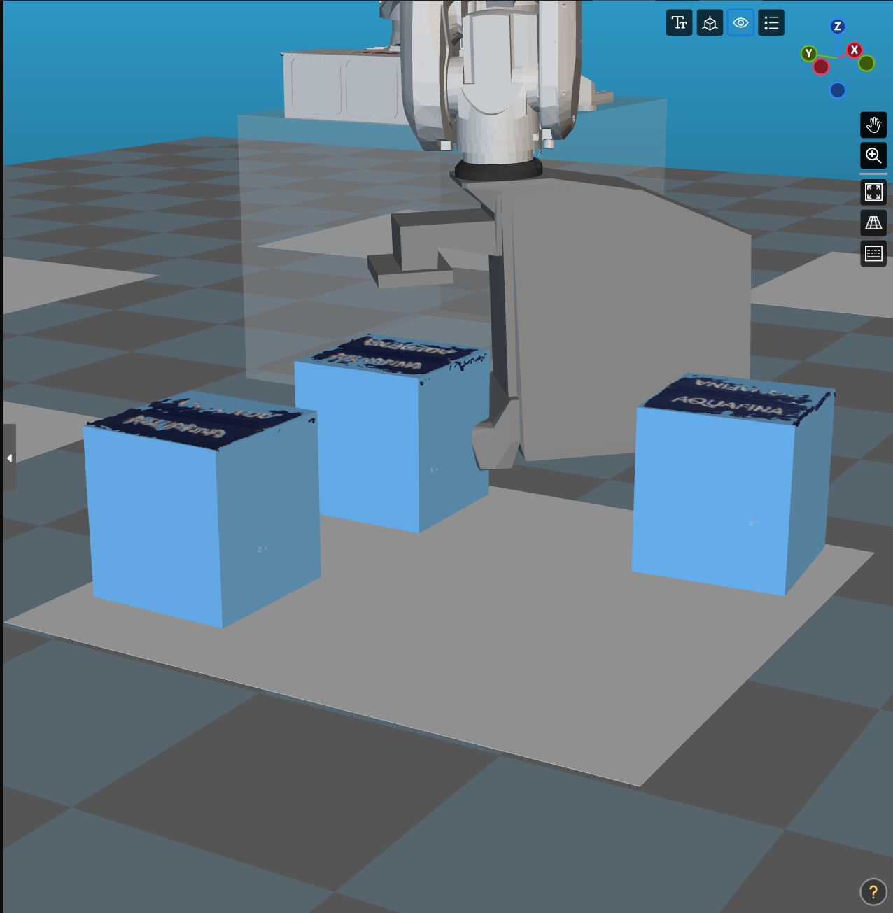
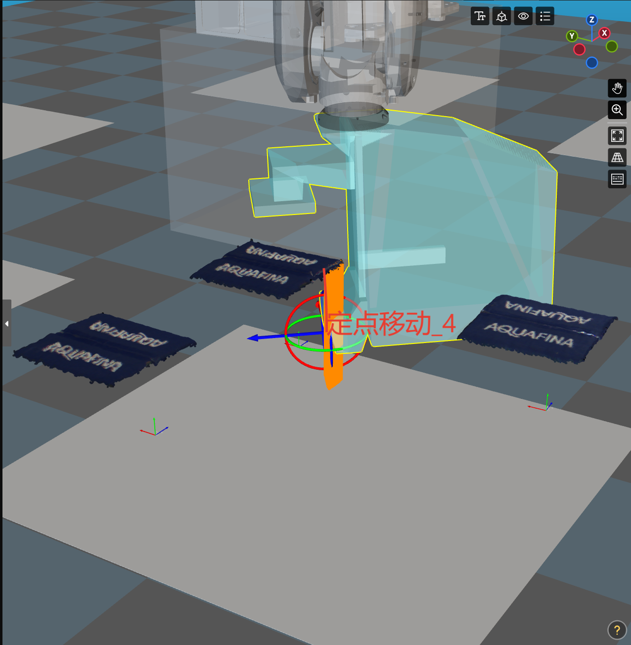
Point cloud column |
When part of the target object is not recognized in the Mech-Vision project and only the point cloud of the object’s upper surface is available, point cloud column can be used to generate an entire collision model for the target object. This effectively prevents collisions caused by the tool passing through the point cloud when picking other target objects, as illustrated in the figure below.
|
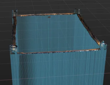
When the bin is deformed, using the point cloud column can generate the collision model of the bin walls accurately, preventing the tool from colliding with the deformed bin walls.
|
|
In depalletizing scenarios where the cartons need to be suctioned from the side surface. |
|
Point cloud cube |
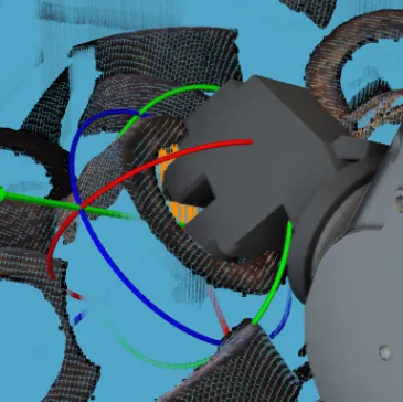
When the tool needs to pass through the target object itself in a horizontal or oblique direction to pick the object, as shown in the figure below. The gripper passes through the ring in an oblique direction and opens the claw from the inside. If the point cloud column is selected, vertical point cloud columns will be generated, and the tool will collide with the point cloud columns inevitably. In such cases, the point cloud cube is recommended for collision detection.
|

Collision Detection Threshold
If the detected collision volume is greater than this threshold, an alarm will be triggered. If the collision volume is less than this threshold, it is considered no collision.
Detect Collisions between Robot and Point Cloud
In general, the robot body rarely collides with the point cloud, so it is not recommended to enable this option. To shorten the time required for path planning and improve the cycle time in the application, please enable point cloud collision detection only for robot parts that are at real risk of collision.
Robot parts to be detected: Enable point cloud collision detection for specific robot parts.
Detect Collisions on Target Objects
Once this option is enabled, you need to configure the collision model for the target object in the target object editor. It is recommended to enable this option only under the following circumstances:
-
Unacceptable collisions may occur between the tool and the target objects.
-
The target object is large, and it is prone to collide with scene objects.
-
There is considerable uncertainty in the motion path (e.g. when using the Smart Path Planning in Bin Step).
-
In mixed-case palletizing scenarios.
Once this option is enabled, Mech-Viz will detect the collisions between the tool and target objects, as well as between the robot and target objects before picking. After picking, Mech-Viz will detect the collisions between the held target object and robot, as well as between the held target object and scene objects.
| Once this option is enabled, please do not adjust the pick points by using pose adjustment Steps in Mech-Vision, as this will cause errors in the pose of the generated collision model, potentially leading to false detections of collisions between the target object and the tool. |
Detect Collisions between Held Target Object, Point Cloud, and Unpicked Target Objects
When the point cloud form for collision detection is set to point cloud column, enabling this option may increase the path planning time. If the path planning time is too long, it is recommended to use a common 3D shape or STL model to generate the collision model in the target object editor or disable this option. Please enable this option only when the entanglement or scraping of the target object significantly affects the picking.
After enabling this option, you can set Collision detection threshold.
| When the collision model is generated by Use common 3D shape in the target object editor, collision detection between held target object and unpicked target objects is not supported. |
Solutions to Common Problems
If the problems described in this interface occur during the actual application, please enable the switch next to the corresponding problem and configure the related parameters as instructed.
Problem 1: When using a vacuum gripper to pick target objects (such as depalletizing cartons), the robot picks the wrong object or squeezes adjacent objects during the picking process
When using a vacuum gripper to pick a target object (such as a box), if the vacuum gripper tightly contacts the target object, the software will detect a point cloud collision between the target object and the tool, causing the pick to fail. By removing the point cloud of the target object, the contact between the tool and the target object will not be detected as a collision. Meanwhile, the point clouds of unpicked objects other than the target object will be retained, allowing normal point cloud collision detection to prevent wrong picks or collisions.
To ensure that the point cloud of the target object is completely removed, it is usually necessary to expand the removal range outward along the surface of the object by a certain distance.
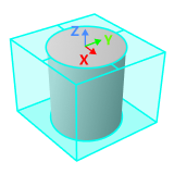
Z-direction point cloud removal range expansion determines the distance expanded outward in the vertical direction (Z-axis) of the target object’s pose based on the original object dimensions. For target objects in the shape of a cylinder or hollow cylinder, this parameter expands the cylinder’s height/length.
X/Y-direction point cloud removal range expansion determines the distance expanded outward in the horizontal direction (XOY plane) of the target object’s pose based on the original object dimensions. For target objects in the shape of a cylinder or hollow cylinder, this parameter expands the cylinder’s (outer) radius.
| Z-direction point cloud removal range expansion | X/Y-direction point cloud removal range expansion | |
|---|---|---|
Cuboid |
|
|
Cylinder |
|
|

Problem 2: The target objects are scattered randomly, making it difficult to calculate a feasible picking path
When the robot is picking target objects (especially the randomly scattered objects), it is inevitable that the contact will be made between the tool and the target object, as well as between the target object and other target objects. If minor contact near the pick point is actually acceptable but is detected as a collision in collision detection, resulting in a planning failure, the following methods can be used to resolve the issue.
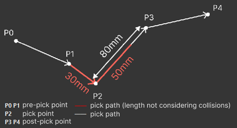
After the Point cloud collision detection or Detect collisions on target objects is enabled, a path length between the pick point and the first waypoint before or after picking will be specified, and the collision detection for the tool and the held target object will be skipped, making it helpful for the calculation of more feasible picking paths. However, collisions between the tool and scene objects or robot links will always be detected.
Enabling this option may increase collision risks. The range exempt from detection should not be excessively large to prevent severe collisions.
If the path length exempt from detection exceeds the path length between the pick point and the first waypoint before or after picking, the effective range will be limited to the shorter path length.
Take the picture below as an example, when the lengths exempt from detection before and after picking are both set as 50mm, while the real effective path length before picking is 30mm.
Problem 3: For mixed-case palletizing, the boxes are prone to collide because the box dimensions vary
A certain thickness will be added to the bottom of the box’s collision model. The thickened collision model will be used in collision detection, thereby avoiding collisions between the box being held and adjacent boxes during palletizing. The Increased thickness at bottom will only take effect when the Mixed Case Palletizing Step is used for path planning.