Camera Mounting Requirements
There are two common mounting modes for the camera: Eye to hand (ETH) and Eye in hand (EIH). You can determine the mode based on the relative position of the camera to the robot and the needs of the overall cycle time. The characteristics and advantages of these two modes are shown in the table below.
Mounting mode |
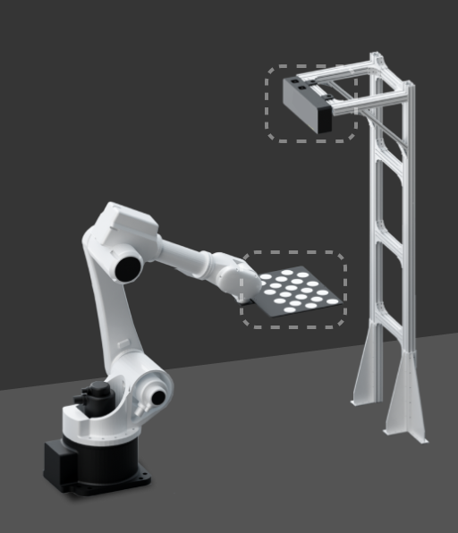
Eye to hand (ETH) |
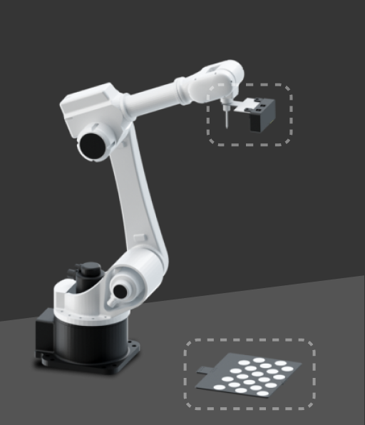
Eye in hand (EIH) |
|---|---|---|
Characteristics |
The camera is mounted on a camera mounting frame independent of the robot. |
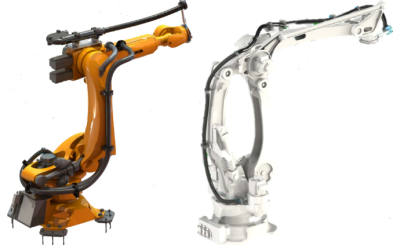
The camera is mounted on the last joint of the robot and moves with the robot. |
Illustration |
|
|
Advantages |
|
|
Additionally, the requirements for mounting the camera mounting frame and cabling vary with different mounting methods, as detailed below.
Camera Mounting Requirements (ETH)
When the camera is mounted on a camera mounting frame (stand) independent of the robot, you need to consider its stability, reliability and cabling to ensure the accuracy of image capturing. Specific notes are as follows:
-
Secure the camera mounting frame
You can use either chemical bolts or expansion bolts to secure the camera mounting frame to the ground, wall, etc., which can provide stable and reliable support to ensure that the camera will not shake.
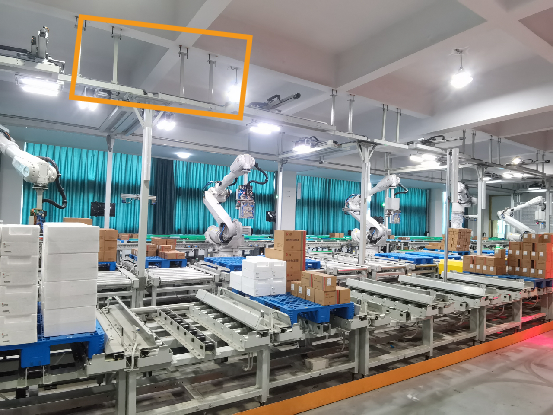
The number and type of foundation bolts depend on the height and structure of the camera mounting frame. When the camera is not mounted on the ground, you may need to reinforce the camera mounting frame by side walls, the floor, or the ceiling, as shown in the figure below.
-
Cabling
Install the camera cables in the cable trays arranged on the surface of the columns for neat and organized routing. This not only ensures the safety and aesthetic appeal of the cables but also facilitates easy maintenance.
-
Adjust camera mounting angle
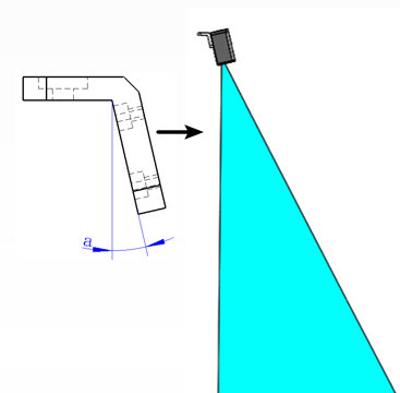
Normally, the camera is mounted vertically downward. However, for project sites with limited ceiling height, you can tilt the camera to adjust the mounting angle. In the early stages of designing your project, it is recommended to perform emulation and simulation tests on your project to ensure that the angle meets the actual requirements.
-
Verify camera’s field of view (FOV)
-
Effective imaging FOV
The effective imaging FOV is the physical region within which the camera can acquire a complete point cloud. Ensure that:
-
The incoming material carrier (e.g., bin or pallet) and all target objects within it are fully contained within this FOV.
-
The region should remain free of any structures, such as safety fences, pipes, the robot body, or grippers, to avoid occlusions or point cloud loss.
Key items to be checked include:
-
The maximum dimensions of the incoming materials, including stacking height, should fall within the camera’s effective imaging FOV.
-
Sufficient clearance (recommended ≥150–200 mm on all sides) should be reserved around the material carrier to accommodate positional deviations.
-
The camera mounting height should correspond to the specified working distance to avoid insufficient FOV due to excessive distance.
-
-
Camera Safety Scanning FOV
Although the camera’s safety scanning FOV is not used for imaging, the following should be ensured in certain applications:
-
The camera mounting frame should not obstruct the robot’s motion path or interfere with the picking pose.
-
-
|
Since the camera position cannot be adjusted after installation, ensure that the FOV fully covers the entire work area before mounting the camera to the mounting frame. |
|
It is recommended to use the 3D Camera Selector tool and Mech-Viz provided by Mech-Mind to perform simulation validation in advance to identify potential FOV occlusion issues. |
Camera Mounting Requirements (EIH)
Pay attention to the following notes when you mount the camera on the last joint of the robot:
-
Install the camera mounting frame
When you install the camera mounting frame (bracket), you should take measures to prevent it from loosening, such as applying thread glue to the mounting bolts, using anti-loosening washers, etc.
-
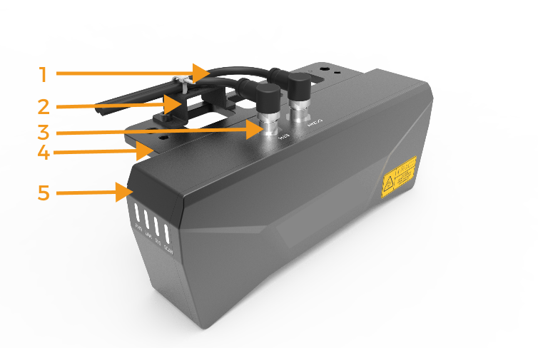
Secure cables
It is necessary to secure the cables near the camera connector to prevent force on it. When bundling cables, it is important to consider the rotational allowance of the robot’s end flange to avoid insufficient cable release, which could lead to pulling on the camera cables, and even cause irreversible damage to the camera cable connector. The way to secure cables is shown in the figure below: 1-camera cable, 2-cable tie mount, 3-cable connector, 4-camera bracket, 5-camera.
-
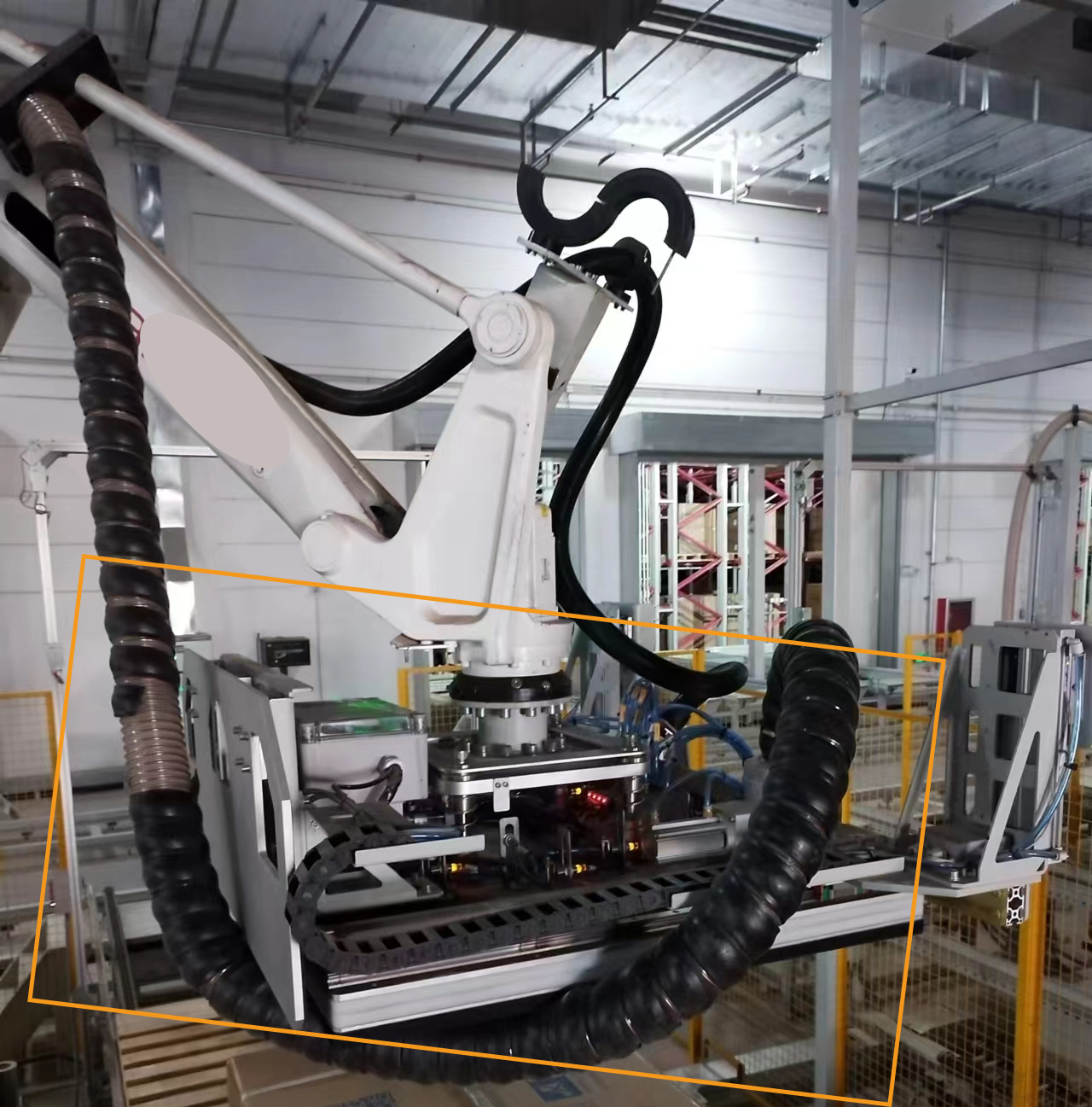
Cabling
The routing of cables should be arranged properly to avoid the cables in the dresspack being too long or too short. The following figure shows an incorrect example of excessively long cables.
-
Cable protection
Use the dresspack to protect cables and pay attention to the following notes:
-
The dresspack shall not use self-winding cable conduits or fabric cable wrap.
-
Choose standard complete sets of corrugated pipe fittings for the dresspack (including but not limited to: tube clamps, half-shells, protection sleeves, etc.).
-
Both the dresspack and cables should be secured and assembled properly to prevent additional torque on the cables during robot motion.
-
-
Verify camera’s field of view (FOV)
-
Effective imaging FOV
The effective imaging FOV is the physical region within which the camera can acquire a complete point cloud. Ensure that:
-
The incoming material carrier (e.g., bin or pallet) and all target objects within it are fully contained within this FOV.
-
No surrounding structures, such as safety fences, pipes, the robot body, or grippers, should intrude into this region, as they may cause occlusions or point cloud loss.
Key items to be checked include:
-
The maximum dimensions of the incoming materials, including stacking height, should fall within the camera’s effective imaging FOV.
-
Sufficient clearance (recommended ≥150–200 mm on all sides) should be reserved around the material carrier to accommodate positional deviations.
-
The camera mounting height should correspond to the specified working distance to avoid insufficient FOV due to excessive distance.
-
-
Camera Safety Scanning FOV
Although the camera’s safety scanning FOV is not used for imaging, the following should be ensured in certain applications:
-
The camera should not collide with surrounding equipment or target objects during robot motion.
-
When the gripper opens or closes, it should not occlude the camera’s view or pose collision risks.
-
-
|
Since the camera moves with the robot, all image-capturing points should remain free of obstructions. |
|
It is recommended to use the 3D Camera Selector tool and Mech-Viz provided by Mech-Mind to perform simulation validation in advance to identify potential FOV occlusion issues. |