Adjust Poses with Pose Adjustment Options (Custom Mode)
This section introduces how to adjust poses with pose adjustment options in the Custom mode.
|
Only one pose adjustment option can be added at one time. However, you can add duplicated pose adjustment options. |
Rotate pose to align with reference direction
Function
This option sets the axis to be fixed and the axis to be rotated, so that the rotation axis of the current pose points to the reference direction.
Usage Instructions
Axis to be fixed
When rotating the pose, this parameter is used to set the axis that needs to be fixed. You can choose between X-axis, Y-axis, and Z-axis according to the actual requirements.
Axis to be rotated
When rotating the pose, this parameter is used to set the axis that needs to be rotated. You can choose between X-axis, Y-axis, and Z-axis according to the actual requirements.
Rotate by a fixed angle increment
This parameter is used to specify the angle increment when rotating the poses. The software will attempt to rotate the poses in the Rotation angle increments.
Set reference direction
There are three methods to set the reference direction, namely, Use robot reference frame, Drag with pose manipulator and Input from external Step, as explained in the table below.
No. |
Method |
Description |
Instruction |
Illustration |
1 |
Use robot reference frame |
Specify the direction of an axis in the robot reference frame as the target direction. |
|
|
2 |
Drag with pose manipulator |
Adjust the position and orientation of the manipulator to set the reference direction. |
|
|
3 |
Input from external Step |
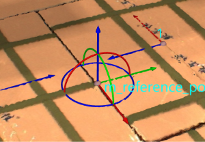
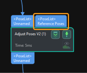
Input a reference pose from other Steps. |
|
|
Rotate pose to point to reference point
Function
This option sets the fixed axis and the pointing axis so that the pointing axis of the current pose points to the reference pose.
Usage Instructions
Set reference pose
There are two methods to set the reference pose, namely, Drag with pose manipulator and Input from external Step, as explained in the table below.
No. |
Method |
Description |
Instruction |
Illustration |
1 |
Drag with pose manipulator |
Adjust the position and orientation of the manipulator to set the reference pose. |
|
|
2 |
Input from external Step |
Input a reference pose from other Steps. |
|
|
Pointing axis
This parameter is used to specify the axis that needs to point to the reference pose. You can choose between X-axis, Y-axis, and Z-axis according to the actual requirements.
Rotate pose by fixed angle
Usage Instructions
Specify rotation axis
This parameter is used to specify the rotation axis. You can choose between X-axis, Y-axis, and Z-axis according to the actual requirements.
Rotation angle
This parameter is used to select the method for inputting the angle of the pose rotation, as explained in the following table.
No. |
Method |
Description |
Instruction |
1 |
Enter manually |
Manually enter the angle of the pose rotation. |
Enter the angle of the pose rotation according to the actual requirements. |
2 |
Input from external Step |
Input the rotation angle from other Steps. |
|
Translate pose along specified direction
Usage Instructions
Translate pose in/along
No. |
Reference frame |
Axis |
1 |
Robot frame |
Positive X-direction, Negative X-direction, Positive Y-direction, Negative Y-direction, Positive Z-direction, Negative Z-direction |
2 |
Target object frame |
X-axis, Y-axis, Z-axis |
Translation distance
This parameter is used to select the method for inputting the translation distance of the pose, as explained in the following table.
No. |
Method |
Description |
Instruction |
1 |
Enter manually |
Enter the distance of the pose translation manually. |
Enter the distance of the pose translation according to the actual requirements. |
2 |
Input from external Step |
Input the translation distance from other Steps. |
|
Align the pose orientation with the target pose orientation
Usage Instructions
Set target pose
There are two methods to set the target pose, namely, Drag with pose manipulator and Input from external Step, as explained in the table below.
No. |
Method |
Description |
Instruction |
Illustration |
1 |
Drag with pose manipulator |
Adjust the position and orientation of the manipulator to set the reference pose. |
|
|
2 |
Input from external Step |
Input a reference pose from other Steps. |
|
|