Interface Introduction
This section introduces the user interface of the path planning tool, including menu bar, toolbar, project resource tree, 3D simulation area, and functional panels.
Toolbar
Option |
Description |
Simulate |
Run the simulated robot |
Stop |
Stop running the simulated robot |
Initial Pose for Planning |
Set the initial pose of the robot for the simulation |
Collision Configuration |
Configure the collision detection settings |
Model Editor |
Open the model editor |
Simulation Speed |
Set the running speed of the simulated robot |
Project Resource Tree
The Resources panel provides the interfaces for the robot, tools, target objects (i.e., the target objects to be picked or processed), scene objects, etc.
Robot
This entry shows the robot model used in the current project.
Click the ![]() button on the right of the Robot in the project resource tree, you can open the Robot Model Library to change robot model.
button on the right of the Robot in the project resource tree, you can open the Robot Model Library to change robot model.
Right-click the robot name, and the following option will appear.
| Option | Description |
|---|---|
Open Robot File Directory |
Open the folder where the robot model file is stored. |
Reload Robot |
Usually used after the parameter file of the local robot model is modified. Click this option to update the robot model and its parameters in the software. |
Click ![]() to make the displayed robot semitransparent, and click
to make the displayed robot semitransparent, and click ![]() to restore to the original display setting.
to restore to the original display setting.
Tools
This entry provides the interface for configuring the tools in the project. Please refer to Tools for how to configure the tools.
Click + to open the Tool Configuration window, where you can add tools.
The default tool is used to avoid errors due to unconfigured end tools.
Right-click the name of a configured tool, and the following options will appear.
| Option | Description | Shortcut |
|---|---|---|
Copy |
Copy the current tool. |
Ctrl + C |
Paste |
Paste the current tool. |
Ctrl + V |
Delete |
Delete the current tool. |
Delete |
Rename |
Rename the current tool. |
None |
Tool Configuration |
Open the Tool Configuration window of the current tool. |
None |
Set As Active Tool |
Set the current tool as the active tool. |
None |
Click ![]() to make the tool model semitransparent, and click
to make the tool model semitransparent, and click ![]() to restore to the original display setting.
to restore to the original display setting.
Target Objects
This entry provides the interface for configuring the target objects in the project. Please refer to Target Object for how to configure the target objects.
Click ![]() on the right to the target object in the project resource tree to open the target object editor for configuration.
on the right to the target object in the project resource tree to open the target object editor for configuration.
Double-click the ![]() button on the left of the target object, and you can view the picking points of a target object. Double-click the name of the target object, and you can directly enter the window of Target Object Editor directly to edit and adjust the target object; double-click the name of the pick point, and you can view and adjust the pick points.
button on the left of the target object, and you can view the picking points of a target object. Double-click the name of the target object, and you can directly enter the window of Target Object Editor directly to edit and adjust the target object; double-click the name of the pick point, and you can view and adjust the pick points.
Floor
This entry provides the interface for modifying the height of the floor and floor display setting.
Right-click the Floor and you can modify the height of it in the pop-up window.
Click ![]() to hide the floor and click
to hide the floor and click ![]() to restore.
to restore.
Scene Objects
This entry provides the interface for configuring the scene objects in the project. Please refer to Scene Objects for how to configure the scene objects.
Click + to open a Scene Object Configuration window, where you can add scene objects.
Right-click the name of a configured scene object, and the following options will appear.
| Option | Description | Shortcut |
|---|---|---|
Copy |
Copy the current scene object. |
Ctrl + C |
Paste |
Paste the scene object. |
Ctrl + V |
Cut |
Cut the current scene object. |
Ctrl + X |
Delete |
Delete the current scene object. |
Delete |
Rename |
Rename the current scene object. |
None |
Scene Object Configuration |
Open the Scene Object Configuration window of the current target object. |
None |
Click ![]() to make the scene object semitransparent; click
to make the scene object semitransparent; click ![]() to make the scene object transparent; and
to make the scene object transparent; and ![]() to restore to the original display setting.
to restore to the original display setting.
You can also drag and drop the scene object name in the Resources panel to make the scene object model a child model or an individual model.
Model Library
This entry provides the interface for importing custom models to the project. All the custom models imported will be displayed in the Model Library, and the models will be categorized according to their formats.
Click + to open the file selection window to import an custom model.
Right-click the imported custom model, and the following options will appear.
| Option | Description | Shortcut |
|---|---|---|
Copy |
Copy the current model. |
Ctrl + C |
Paste |
Paste the copied model. |
Ctrl + V |
Delete |
Delete the current model. |
Delete |
Model Configuration |
Open the Model Configuration window of the current model. |
None |
Model Editor |
Open the model editor and the current model will be used as the reference model. |
None |
Open Folder |
Open the folder where the model file is stored. |
None |
3D Simulation Area
The robot, scene objects, tools, target object models, robot motion path, pick points, and collisions will be displayed in the 3D simulation area. You can also drag to move the models of scene objects in this area.
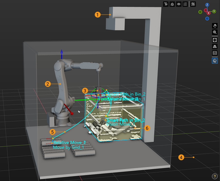
No. |
Description |
1 |
Scene objects |
2 |
Robot |
3 |
Tools |
4 |
Floor |
5 |
Planned path |
The 3D simulation area can display the motion path of both the real robot in actual application and the simulated robot in project simulation.
|
|
6 |
Vision result |
The vision result returned by the vision service will be displayed in the 3D simulation area.
|
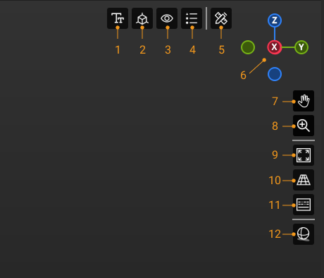
Introduction to Components
No. |
Description |
1 |
Click this icon to view the menu showing the font size and axis size. |
2 |
Click this icon to view the menu showing the visibility of reference frames. |
3 |
Click this icon to view the menu showing the visibility of the components in the vision results. |
4 |
Click this icon to view the menu showing the color legend of vision poses. For information on the pose status corresponding to different color legends, please refer to Pose Status Details. |
5 |
Click this icon to enable the measurement feature. For operation instructions, refer to Measurement Mode. |
6 |
The navigation gizmo shows the current view in the workspace. |
Click the icon of each axis (X, Y, Z, -X, -Y, -Z) to align the view with the axis. Press and hold the left mouse button and drag the navigation gizmo to rotate the view. |
|
7 |
Pan the view |
Press and hold this icon (or Shift + Scroll wheel), and then drag the icon to pan the view. |
|
8 |
Zoom in/out |
Press and hold this icon, and then drag it upward (or scroll the mouse forward) to zoom in, or drag it downward (or scroll the mouse downward) to zoom out. |
|
9 |
Fit the view |
10 |
Click this icon to switch to perspective/orthographic view. |
11 |
Show pressed keyboard keys and mouse buttons |
Once this icon is selected (highlighted in blue), the keyboard keys and mouse buttons you pressed will be displayed in the lower right corner in the 3D simulation area. |
|
12 |
Click this icon to show ambient occlusion of the 3D model, so as to enhance the 3D effect of the simulation. |
Functional Panels
The functional panels include Workflow, Robot, Plan History, and Log.
Workflow
You can configure the workflow in this panel.
-
Click Add to create a new workflow.
-
Click Delete to delete the workflow.
-
Click Rename to edit the name of the current workflow.
-
Click
 to switch the workflow.
 -
Select a step, and its parameters will be displayed on the right panel.
-
Move the mouse cursor to the line connecting the Steps and then click
 to insert a Step.
 -
Double-click the Step name to modify it. (The name of Global Configuration cannot be modified.)
Plan History
On this panel, you can view the plan history of Mech-Viz in detail. You can also use the plan history to troubleshoot problems, and improve the project logic. For details, please refer to Plan History.
This functional panel displays parameters related to the plan history.
Option |
Description |
Total execution time |
The time taken from when the project starts running/simulating until it stops. |
Total planning time |
The total elapsed time used for path planning. |
Click to view target object/pick point details |
Once enabled, if corresponding vision results exist, selecting a target object or pick point to query plan history, or clicking a plan history entry will open a pop-up window displaying the details of the pick point or target object. |
Click to zoom collision details |
Once enabled, clicking a plan history entry that failed due to a collision will automatically adjust the view in the 3D simulation area, focusing on the two colliding objects. |
Minimum animation duration |
Upon the selected plan history entry, the corresponding animation of the complete trajectory will be played, and this parameter specifies the minimum duration for the animation playback thereafter. |
Clear plan history |
Clear all plan history currently displayed in the panel. |
Import |
Load plan history files from the specified directory. |
Export |
Export all the current plan history to a specified directory. |
Open plan history folder |
Open the default folder that stores the plan history. |
Right-click on an entry in the plan history, you can see the following options:
Option |
Description |
Shortcut |
Copy |
Copy the selected content. |
Ctrl + C |
Collapse All |
Collapse all sub-nodes in the panel and only displays the parent nodes. |
N/A |
Delete Selected Plan History |
Delete the selected plan history item. |
N/A |
Log
On the log panel, you can view the software log in detail and manage the log settings at the bottom of the panel.
When encountering issues while using the software, you can check the logs. You can also export the log and send it to Technical Support to facilitate the troubleshooting process.
|
Click one log entry and press Ctrl+C, and the entry will be copied to your clipboard. |
Option |
Description |
D: Debug |
Screen out the logs to be displayed according to their levels. Logs under selected levels will be displayed. You can select multiple levels. |
i: Info |
|
W: Warning |
|
E: Error |
|
Clear |
Clear all log messages on the page. |
Export |
Export the log messages to the HTML file. The exported files are located in the logs folder in the Mech-Viz installation directory. |
Open folder |
Click to open the logs folder in Mech-Viz’s installation directory. The logs folder contains log files recorded by date. |