Analyze Extrinsic Parameter Error in ETH Setup
Ensure the Calibration Board Has Been Mounted
To obtain the pose of the calibration board and the scene point cloud containing calibration board for the ETH extrinsic parameter error evaluation, it is necessary to check the calibration board before proceeding. Ensure that the calibration board is mounted on the robot. For more instructions, please refer to Calibration Board Mounting Method.
Build Project to Obtain Calibration Board Poses
-
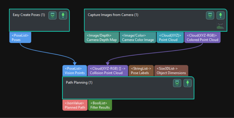
Add the “Capture Images from Camera” Step.
Create a new project and add the “Capture Images from Camera” Step, or select the Step in an opened project. Click the Select camera button in the Step Parameters panel to select and connect the camera. Then select the Camera Calibration Parameters to be checked.
-
Add the “Path Planning” Step.
Add the “Path Planning” Step and connect the Colored Point Cloud output port of the “Capture Images from Camera” Step with the Collision Point Cloud input port of this Step.
-
Add the “Easy Create Poses” Step.
Add the “Easy Create Poses” Step and connect the Poses output port with the Vision Points input port of the “Path Planning” Step.
The built project is shown as below.
-
Enter the simulation interface.
Click Config wizard in Step Parameters panel of the “Path Planning” Step to enter the 3D simulation area.
Synchronize the Pose of the Real Robot and Obtain the Scene Point Cloud Containing the Calibration Board Point Cloud
-
Click Config wizard in Step Parameters panel of the “Path Planning” Step to enter the 3D simulation area.
-
Synchronize the pose of the real robot with that of the simulated robot in the “Path Planning” Step, so that the poses of the simulated robot in the 3D simulation area and the real robot will be the same.
-
Click the Simulate button to visualize the scene point cloud containing the calibration board. (Please ignore the error message after clicking Simulate.)
Create Virtual TCP on the Calibration Board
-
Add an end tool to the resources in the path planning tool.
-
Check the visualization of the end tool in the 3D simulation area, and adjust the parameters to make the TCP coincide with a circle center on the calibration board (the pose axis should coincide with the cross in the circle and the XOY plane should be closely aligned with the calibration plane).
-
Enter a tool name and click OK to finish creating the virtual TCP.
Check Extrinsic Parameters at Other Positions in the Workspace
-
Move the real robot using the teach pendant to other positions in the workspace.
-
Synchronize the pose of the real robot with that of the simulated robot in the “Path Planning” Step, so that the poses of the simulated robot in the 3D simulation area and the real robot will be the same.
-
Click the “Simulate” button to obtain the new scene point cloud containing the calibration board.
-
Check if the virtual TCP added previously coincides with the circle center on the calibration board.
Other Checking Suggestions
If there is a significant error in the extrinsic parameters, please refer to the following suggestions:
-
The accuracy of the extrinsic parameters is mainly influenced by the absolute accuracy of the robot. Please check the absolute accuracy of the robot.
-
You can try creating different point cloud models at different positions or jogging the robot to record different pick points to compensate for the robot’s absolute accuracy.