Box Depalletizing—One by One
When the Picking Method is set to Box depalletizing, and the Depalletizing Mode is set to One by one, you can configure the following parameters.
In addition, you should refer to Configure End Tool to configure the corresponding end tool.
Move-Type Step Common Parameters
Send Waypoint
Selected by default, i.e., send the current waypoint to the receiver, such as the robot. Once deselected, the current waypoint will not be sent. However, the waypoint will remain in the planned path.
Try Continuously Running through Succeeding Non-Moves
Unselected by default. When non-move Steps, such as Visual Recognition, Set DO, Check DI, etc., are connected between move-type Steps, the sending of the waypoints will be interrupted, and the real robot will take a short pause, reducing the smoothness of running.
When this parameter is selected, the project will continue to run without waiting for the current move-type Step to complete execution, and therefore the robot can move in a smooth way without pauses. However, selecting this parameter may cause the execution of the Step to end prematurely.
Why will this feature cause the execution of the Step to end prematurely?
Mech-Viz will send multiple waypoints simultaneously to the robot when the project is running. When the currently returned JPs of the robot correspond to the last waypoint sent by Mech-Viz, Mech-Viz will assume that the robot has moved to the last waypoint.
For example, there are 10 move-type Steps in a path, and the pose of the 5th move-type Step is the same as that of the last move-type Step. When the robot moves at a low speed, the current JPs will be sent to Mech-Viz after the robot moves to the 5th waypoint. Since the poses of the 5th move-type Step and the last move-type Step are the same, Mech-Viz may mistakenly determine that the robot has reached all waypoints and prematurely ends the command.
Do Not Check Collision with Placed Target Object
Once Detect collisions on target objects is enabled in the Collisions panel, selecting this parameter will disable the collision detection between the robot, robot tool, and placed target objects. Typically, this parameter is selected in the move-type Step following the Step whose Pick or place is set to Place to avoid false collision detections.
Application Example:
The TCP of a depalletizing vacuum gripper is usually set inside the model rather than on the surface of the vacuum gripper. As a result, when picking a box, the vacuum gripper model may overlap with the box model. However, the software does not detect collisions between the end tool and the picked target object, so no collision alarm will be triggered during picking. Once the robot places the box down, the picked box model becomes a scene model, and the software will start to detect the collision between the end tool and the box’s scene model, triggering a collision alarm and preventing the completion of the palletizing task.
Once this parameter is selected, no collision between the robot, end tool, and the model of the placed target object will be detected, and the above issue will be resolved.
Point Cloud Collision Detection Mode
Usually, Auto can be selected, i.e., directly apply the Point cloud collision detection settings in the Collisions panel. For the Steps between picking and placing, Check collision can typically be selected.
Auto |
Default setting. Once Detect collisions on target objects is enabled in the Collisions panel, only point cloud collisions of the “Vision Move” Step and the “Relative Move” Steps that depend on the “Vision Move” Step will be detected, while other move-type Steps will not be detected. |
Do not check collision |
Point cloud collisions of all move-type Steps will not be detected. |
Check collision |
Point cloud collisions of all move-type Steps will be detected. |
Ignore Target Object Symmetry
This parameter is only visible when the Waypoint type of the move-type Step is set to Target object pose.
The target object symmetry here refers to the Rotational symmetry of held target object predefined in the target object editor during collision model setup.
None |
Default setting, i.e., do not ignore symmetry on any axis. |
Around target object frame Z axis |
Only ignore symmetry around the Z-axis. |
Around target object frame X&Y axes |
Ignore symmetry around the X-axis and Y-axis. |
Around all axes |
Once the symmetry around all axes is ignored, the robot will place the object strictly according to the target object pose. |
| When the move-type Steps are used to place the target objects, the consistency of the placing poses of the target objects cannot be guaranteed once the rotational symmetry is applied. If you want all target objects to be placed strictly according to a specific rule, ignore the symmetry of the target object around all axes. |
Plan Failure Out Port
Once this parameter is selected, a Plan failure exit port will be added to the Step.
If the path planning of the current Step succeeds, the workflow will continue along the Success exit port. If the path planning of the current Step fails, the workflow will proceed along the Plan failure exit port. If multiple move-type Steps with “Plan failure” exit ports display in the same plan history entry, the workflow will proceed along the “Plan failure” exit port of the first move-type Step.
Held Target Object Collision Detection Settings
Before configuring this parameter group, please go to the Collisions panel and enable Detect collisions on target objects.
| Disabling collision detection will increase the collision risks. Please select the following parameters with caution. |
Do Not Check Collision with Scene Objects
Once this parameter is selected, collisions between the held target object and the scene model will not be detected, reducing the computational load of collision detection in the software, speeding up path planning, and optimizing the overall cycle time.
Do Not Check Collision with Robot
Once this parameter is selected, collisions between the held target object and the robot will not be detected, reducing the computational load of collision detection in the software, speeding up path planning, and optimizing the overall cycle time.
Do Not Check Collision with Point Cloud
Once Point cloud collision detection is enabled in the Collisions panel, selecting this parameter will stop detecting collisions between the held target object and the point cloud, further reducing the software’s computational load, shortening path planning time, and enhancing the overall cycle time.
Vision Result Global Usage
Reuse Vision Result
Usage Scenario
This parameter is mainly used in scenarios where one captured image is used to guide multiple pickings, such as depalletizing, provided that picking any one object does not affect the poses of other objects.
Description
When this parameter is not selected, each time “Vision Move” plans a robot picking path successfully, the rest unused pick points will be discarded.
If this parameter is enabled, the unused pick points and the pick points that failed in the previous planning will be retained and used in the next planning. The same vision result will be reused for multiple picks until all pick points have been used, without the need to capture a new image.
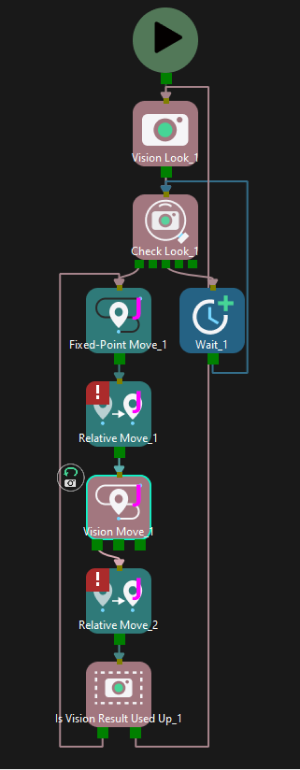
This feature should be used with the “Whether Pick Points Are Used Up” Step.
Application Example
Share Vision Result
Usage Scenario
This parameter is applicable when multiple “Vision Move” Steps select the same vision service and need to share the same vision result.
Description
This parameter enables multiple “Vision Move” Steps in which the same vision service is selected to share the vision result.
When one “Vision Move” Step plans successfully, the corresponding pick point will be used, and the remaining unused pick point will be retained and used by other “Vision Move” Steps that share the same vision result. After all “Vision Move” Steps that share the vision result complete planning, the remaining pick points will be discarded.
This feature can be used in conjunction with the “Reuse Vision Result” feature. If “Reuse Vision Result” is also enabled, any remaining pick points will not be discarded even after all shared “Vision Move” Steps have completed planning in the current cycle, but will instead be retained for reuse in the next cycle until all pick points are used.
Supplementary Features
Re-Locate Bin with Vision
| When the Port Type of the Output Step in Mech-Vision is set to Custom, please select the Update Bin Pose with Vision parameter here to update the poses of the bin or other scene objects. When the Port Type of the “Output” Step in Mech-Vision is set to Predefined (vision result), please select the Update Scene Object parameter in the Step Parameters of the “Output” Step, and use the Update Scene Objects Step in Mech-Viz to update the poses of scene objects. |
Once the Update Bin Pose with Vision parameter is selected, the bin will be recognized and located simultaneously while the camera captures the image for target object recognition. Therefore, the bin pose in the simulation area can be updated dynamically, which facilitates the collision detection algorithm to effectively prevent the robot from colliding with the bin.
This feature will provide three fields, scene_object_names, scene_object_poses, and scene_object_sizes, in the vision result to define the name, pose, and dimensions of the scene object to be updated.
Filter Vision Result
-
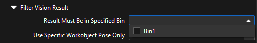
Result Must Be in Specified Bin
This feature limits that the vision result received by the current “Vision Move” Step must be in a specified bin. The vision result out of the effective bin range will not be used.
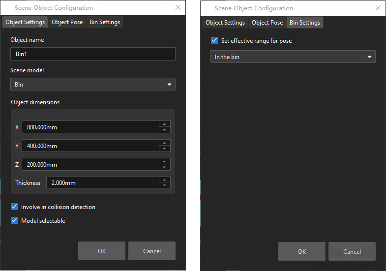
Each bin’s effective range for vision result can be configured separately in the corresponding configuration window. Only bins with “Set effective range for pose” enabled can be selected in the drop-down menu.
Application Example
Add “Bin1”, and enable the “Set effective range for pose” parameter for this bin.
Select “Bin1” in the drop-down menu.
-
Filter Poses
Use all
Do not filter poses. All poses in the vision result will be used for path planning.
Filter by target object name
Once this option is selected, select the target object configured in the target object editor in the drop-down list of the Use Specified Target Object Name parameter. Filtering poses based on multiple target object names is supported.
Filter by pick point name
Once this option is selected, select the pick point name in the drop-down list of the Use Specified Pick Point Name parameter. Filtering poses based on multiple pick point names is supported.
Filter by pick point label
Once this option is selected, the poses can be filtered by the specified pick point labels. After entering the label in the parameter field of Use Specified Pick Point Label, only pick points with the specified label will be used for path planning. Filtering poses based on multiple deep learning labels and numeric labels set in the target object editor are supported. Commas (,), colons(:), or semicolons (;) can be used as separators, with no spaces required between labels and separators.
Avoid Picking on Same Target Object
This parameter group is mainly used to avoid picking on the same pick point in scenarios where the object cannot be picked successfully.
Once the Filter Out Unlikely Pick Point parameter is selected, you can adjust the following parameters.
-
Filter Subject
-
Pick point: Only pick points with high failure rates will be deprioritized in the picking and discarded in some rounds.
-
All pick points on the same target object: if any one pick point on the target object is considered to have a high failure rate, all pick points on this object will be deprioritized in the picking and discarded in some rounds.
-
-
Priority Downgrade Radius
A sphere with this parameter value as its radius and the pick point successfully planned in the last round as its center will be introduced. If a pick point in the latest vision result falls within this sphere, the pick point will be put off for picking with a decreased picking priority.
-
Discard Attempt Radius
A sphere with this parameter value as its radius and the pick point successfully planned in the last round as its center will be introduced. If a pick point in the latest vision result falls within this sphere, the pick point will be discarded in this round of planning.
For example, if the robot only moves the crankshaft but fails to pick it on the first attempt, there is a possibility of successful picking on the next attempt. Therefore, Priority Downgrade Radius can be set to downgrade the priority of the pick point, while the pick point will not be discarded. When the robot fails to move the crankshaft at all in the first attempt, it is highly unlikely that the crankshaft can be picked successfully in the next attempt, and therefore Discard Attempt Radius can be set to discard the pose directly.
|
When Filter Subject is set to Pick point, the maximum list length for pick points with high picking failure rates is internally fixed at 100, and no configurable parameter is available. If the number of pick points in a single vision result is fewer than 100, the list length matches that number. When the list length exceeds the upper limit, the pick point that is added to the list earliest will be removed from the list and can be used in the next round of planning. When Filter Subject is set to All pick points on the same target object, the maximum list length for target objects with high picking failure rates is internally fixed at 100, and no configurable parameter is available. If the number of target objects in a single vision result is fewer than 100, the list length matches that number. When the list length exceeds the upper limit, the target object that is added to the list earliest will be removed from the list and can be used in the next round of planning. |
Vacuum Gripper Offset
During the depalletizing process of the boxes, the fixed and non-replaceable vacuum grippers are usually used. Due to various sizes of the boxes, the vacuum gripper need to handle different boxes of various sizes. To avoid picking non-target boxes, the robot may not pick the target box with the center of the vacuum gripper. Instead, the corner or other parts of the vacuum gripper will be used. By setting the Offset Approach and configuring theVacuum Gripper Orientation, the problem of picking the wrong box can be effectively avoided, ensuring stable picking of boxes of various dimensions.
There are four offset strategies in total, and each strategy contains different parameters.
Default strategy
The software sequentially applies three strategies—Center to center, Edge midpoint to edge midpoint, and Corner to corner—to attempt the vacuum gripper offset.
Custom strategy priority
The software adheres to user-defined offset priorities to attempt the vacuum gripper offset.
There are three custom strategies in total, which are Center to center, Edge midpoint to edge midpoint, and Corner to corner. You can specify the attempt sequence for each strategy by configuring the Offset Priority parameter group.
-
Center to center: The center of the activated section of the vacuum gripper matches that of the box.
-
Edge midpoint to edge midpoint: The edge midpoint of the activated section of the vacuum gripper matches that of the box.
-
Corner to corner: The corner of the activated section of the vacuum gripper matches that of the box.
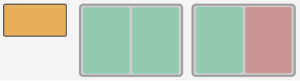
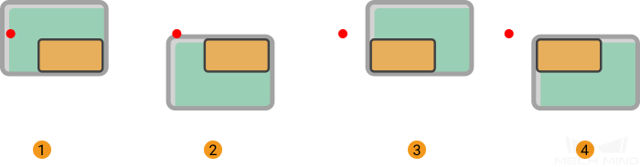
In the figure below, the orange rectangle represents the box, and the gray rectangle represents the vacuum gripper. The green part of the vacuum gripper indicates that the section is activated, while the red part indicates that the section is deactivated.
-
When a single section is activated
The figures below demonstrate the effects of using Center to center, Edge midpoint to edge midpoint, and Corner to corner from left to right.
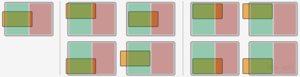
-
When both sections are activated
The figures below demonstrate the effects of using Center to center, Edge midpoint to edge midpoint, and Corner to corner from left to right.
-
The effect is similar when there are more than two activated sections of the vacuum gripper.
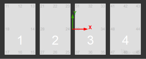
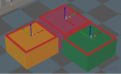
By edge/corner ID sequence
The software attempts the offset according to the user-specified Edge/corner ID sequence (e.g., 11, 21, 31, 41).
The edge/corner IDs are generated automatically in the vacuum gripper configurator. The two-digit numbers at the edge of each section are edge/corner IDs, as shown below.
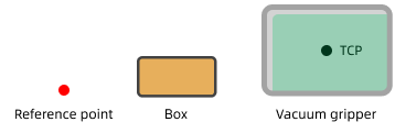
By distance to reference point
You need to set a reference point to enable this feature. The offset strategies will be sorted according to the distance between the TCP and the reference point, and the offset strategy with a TCP closer to the reference point has a higher priority.
-
Reference Point X/Y
Specify the position of the reference point. The reference point will appear in the 3D simulation area.
-
Keep Only High Priority Offset
Only offset solutions with a shorter distance to the reference point will be kept.
-
Max Plan Result Count
The maximum number of offset solutions that will be kept.
If there are 4 possible solutions for the vacuum gripper offset in total, and the value of this parameter is set to 2, the 2 solutions in which the vacuum gripper TCPs are closer to the reference point will be kept.
If there are 2 possible solutions for the vacuum gripper offset in total, and the value of this parameter is set to 4, only 2 solutions will be kept.
-
Application Example
The software will attempt the offsets in the order shown below.
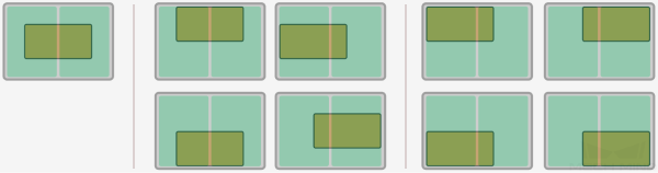
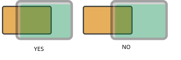
Box Surface Coverage Lower Limit
This parameter specifies the minimum proportion of a box’s upper surface covered by the vacuum gripper when the vacuum gripper attempts to pick a box. If the coverage is below the threshold, it is considered that the vacuum gripper cannot attach to the box firmly and the picking is not allowed.
In addition, when the upper surface of a single box is larger than the entire vacuum gripper, and all sections of the vacuum gripper are activated, the coverage can reach 100%.
Supposing that this parameter is set to 50%, the picking feasibilities are shown as below.
Vacuum Gripper Orientation
This parameter specifies the orientation of the vacuum gripper relative to the box group during picking.
-
Free: The orientation of the vacuum gripper is not specified.
-
Custom: You can set the Vacuum Gripper X-Axis Direction and Orientation Reference, and there are four relative positional relationships in total:
-
X-axes of objects are parallel to that of the vacuum gripper.
-
X-axes of objects are perpendicular to that of the vacuum gripper.
-
The X-axis of the vacuum gripper is parallel to the direction along which the boxes are grouped.
-
The X-axis of the vacuum gripper is perpendicular to the direction along which the boxes are grouped.
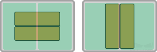
The figure on the left shows the effect when the X-axis of the vacuum gripper is parallel to the long edge of the box group, and the figure on the right shows the effect when the X-axis of the vacuum gripper is perpendicular to the long edge of the box group.
-
Box Drop Detection
In actual box depalletizing projects, DI check points will be added to the working surface of the vacuum gripper to monitor whether the boxes are dropped during picking and placing by comparing the sensor signal changes.
After the DI check points are added to the vacuum gripper configurator, the software will determine which sensors on the working surface of the vacuum gripper are covered by the picked boxes, and therefore the DI signals that should be detected can be confirmed.
Remove Edge DI
In actual depalletizing process, when the sensors attached to the vacuum gripper near the edge of the box, the software may mistakenly detect that the box is dropped due to large gap between boxes, loose suction at the edge, or other reasons.
To prevent these issues, you can select this parameter and set Box Edge Removal Distance.
Box Edge Removal Distance
DI sensors that are within the removal range will not be taken into account in the box drop detection.
The width of the red frame shown in the figure below represents the Box Edge Removal Distance. For actual application, please adjust this parameter according to the on-site requirement.
Target Object Count
Picked Object Limit
Once this option is selected, you can set the Max Picked Objects and other parameters.
Max Picked Objects |
The maximum number of target objects allowed to be picked during the project execution. |
Total Picked Objects |
The total number of target objects picked so far. |
Picked Objects This Time |
The number of target objects picked this time. When the picking method is set to Regular picking or Box depalletizing with the Depalletizing Mode of One by one, this value is fixed at 1 if the picking proceeds normally. |