Hand-Eye Calibration in the Eye-to-Eye Setup
This how-to guide introduces how to complete the hand-eye calibration in the eye-to-eye (ETE) setup.
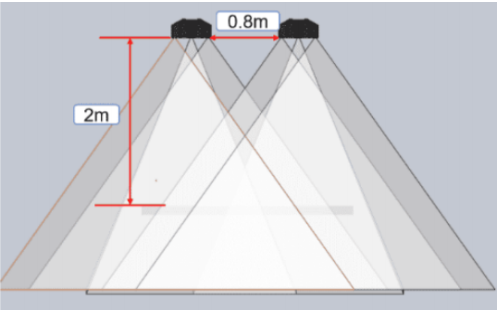
In the ETE setup, two cameras are used, one as main camera and the other as sub-camera, as shown in the figure below. ETE calibration includes calibrating the extrinsic parameters of the two cameras and calibrating the pose relationship between them.
Preparation before Calibration
Before hand-eye calibration, you need to finish the following preparations:
Complete the Vision System Hardware Setup
Please refer to Vision System Hardware Setup to complete the system hardware setup.
You need to use Mech-Eye Viewer, and Mech-Vision&Mech-Viz during hand-eye calibration. Please ensure that they have been installed and are running the latest versions.
Complete the Robot Communication Configuration
If the robot uses the Standard Interface to communicate with the Vision System, please set up the Standard Interface communication with the robot. According to the robot brand used in your project, you can complete the Standard Interface communication configuration by referring to the “Set up Standard Interface Communication” guide for the corresponding robot brand in Standard Interface Communication.
If the robot uses the Master-Control to communicate with the Vision System, please set up the Master-Control communication with the robot. According to the robot brand used in your project, you can complete the Master-Control communication configuration by referring to the “Set up Master-Control Communication” guide for the corresponding robot brand in vMaster-Control Communication.
Prepare the Materials Required for Calibration
The hand-eye calibration in the ETE setup needs to use the calibration board. Please prepare the calibration board according to the following requirements:
-
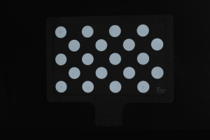
Ensure that the circles of the calibration board are clearly visible and without obvious scratches, and the board does not suffer from deformations.
-
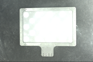
In the ETE setup, mount the robot-specific bracket for calibration board onto the robot flange, and then mount the calibration board onto the bracket. Ensure that the calibration board is securely mounted, located at the center of the camera’s field of view, and kept as parallel as possible to the plane where the camera is located, making it as perpendicular as possible to the Z-axis of the camera reference frame.
If an undetachable gripper is connected to the robot flange, you can attach the calibration board directly to the gripper.
In addition, before calibration, move the robot to the starting point for calibration, that is, the bottom middle of the overlapped area of the two cameras’ field of view.
Check the Point Cloud Quality of the Calibration Board
| The point cloud quality of the calibration board will affect the accuracy of hand-eye calibration. Check the point cloud quality of the calibration board to ensure the accuracy and reliability of the calibration results. The calibration process includes the step of checking the point cloud quality of the calibration board. You can also check the point cloud quality of the calibration board before starting the calibration to save time. |
-
Place the calibration board horizontally at the center of the working plane within the camera’s field of view.
-
Open the Mech-Eye Viewer software, select the camera used by the project, and then select the “calib” parameter group and adjust camera parameters.
-
Adjust the 2D parameters to ensure that the overall 2D image is not too dark, and each calibration circle is clearly visible.
-
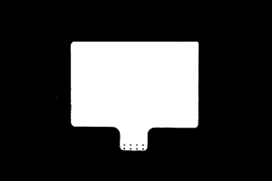
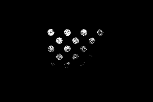
Adjust the 3D parameters to ensure that each calibration circle on the calibration board is complete and visible.
If the on-site ambient lights are not ideal and affect the quality of 2D images and point clouds, you can use shading or supplemental light to improve the lighting conditions.
-
Make sure that the point cloud quality of the calibration board is up to standard after completing the preceding steps.
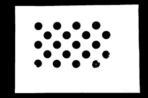
Normal Overexposed Underexposed 2D image
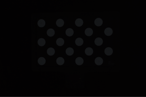
Point cloud
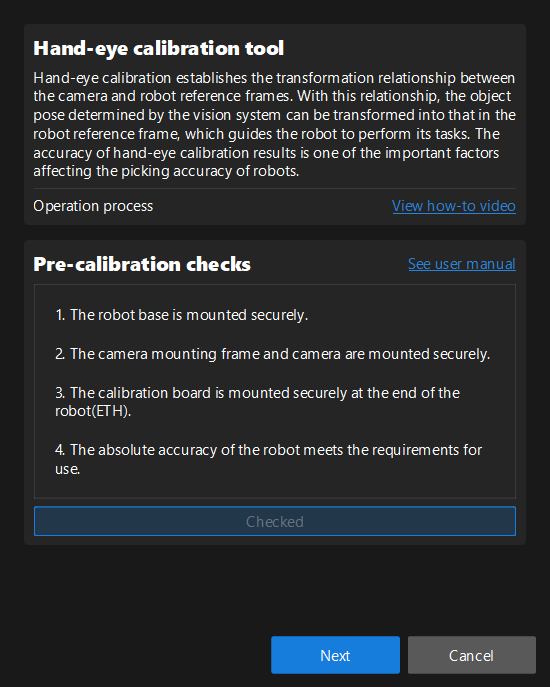
Complete Pre-calibration Checks
Please refer to Pre-calibration Checks and complete the following checks:
-
Confirm that the robot base is mounted securely.
-
Confirm that the camera mounting frame and camera are mounted securely.
-
Confirm that the absolute accuracy of the robot meets the requirements for use.
-
Verify robot model parameters.
-
Confirm that the camera is warmed up.
Perform Calibration
Two methods for ETE calibration are described below.
-
Perform ETE calibration by loading existing calibration parameters
Checking the point cloud view by loading existing calibration parameters is not supported.
-
Perform ETE Calibration Directly
When performing ETE calibration directly through the calibration tool, the eye-in-hand (EIH) setup is not supported. If the cameras have to be mounted in the EIH setup, you can view the fusion effect for dual camera calibration through the Mech-Vision project.
Perform ETE calibration by loading existing calibration parameters
After calibrating the extrinsic parameters of the two cameras separately, you can use the calibrated extrinsic parameters to calculate the pose relationship between the two cameras, i.e., use the ETE calibration procedure to directly calculate the pose relationship between the two cameras.
To do so, follow these steps:
-
Open Mech-Vision, and click the Camera Calibration button in the toolbar. The Configuration before Calibration window will be prompted.
-
After confirming that pre-calibration checks are completed, click I’ve finished all checks, and then click Next.
-
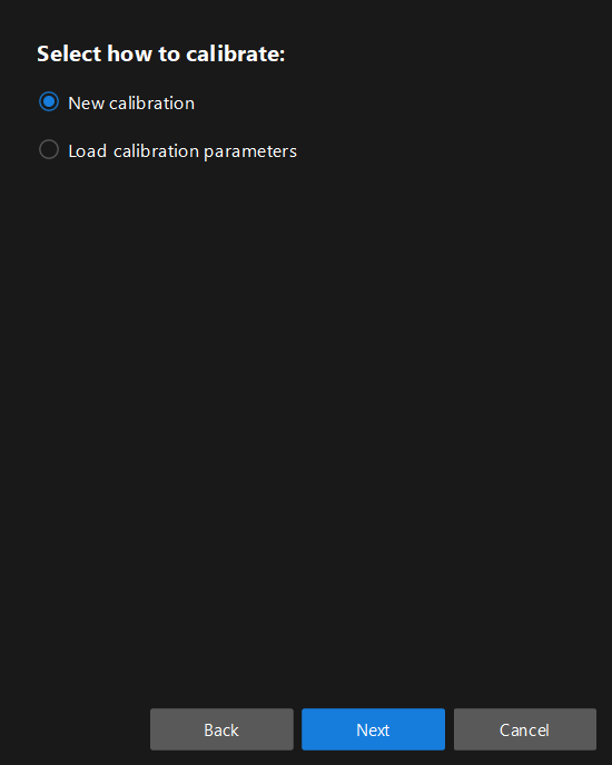
In the Select how to calibrate window, select the New calibration radio button, and then click the Next button.
-
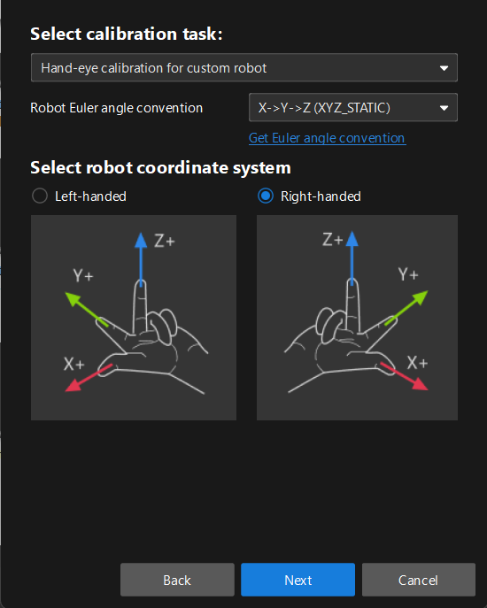
In the Select calibration task window, select Hand-eye calibration for custom robot from the drop-down list box, specify the Robot Euler angle convention parameter, select the robot coordinate system type, and then click the Next button.
-
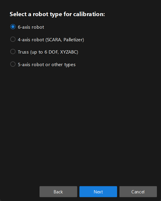
In Select a robot type for calibration window, select a robot type among 6-axis robot, 4-axis robot (SCARA, Palletizer) or 5-axis robot or other types radio button, and then click the Next button.
-
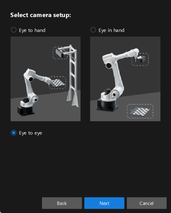
In the Select camera setup window, select the Eye to eye radio button, and then click the Next button.
-
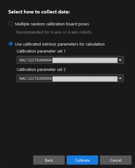
In the Select how to collect data window, select the Use calibrated extrinsic parameters for calculation, choose two camera’s extrinsic parameter files, and then click the Calibrate button. The Calibration (Eye to Eye) window will be prompted.
-
In the Connect to camera step, select the camera to connect in the Camera ID list, and then click the
 button to connect to it.
 -
Repeat the preceding step to connect to the second camera, and then click the Next button on the bottom bar.
-
In the Calculate extrinsic parameters step, click the Calculate extrinsic parameters button.
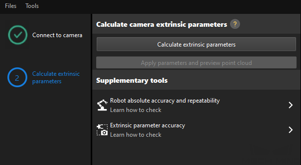
After the camera extrinsic parameters have been calculated, you can view the fused point cloud in the Point cloud viewer panel.
Perform ETE Calibration Directly
Pre-calibration Configuration
If the robot supports the Standard Interface or Master-Control communication mode, please complete pre-calibration configuration according to the section Pre-calibration Configuration for automatic calibration in the ETH setup.
Compared with the automatic calibration in the ETH setup, the following operation is different. During the pre-calibration configuration in the ETE setup, you need to select the Eye to eye radio button in the Select camera setup window.
If the robot does not support the Standard Interface or Master-Control communication mode, please complete pre-calibration configuration according to the section Pre-calibration Configuration for manual calibration using the multiple random calibration board poses method in the ETH setup.
Compared with the preceding calibration process, the following operations are different during the pre-calibration configuration in the ETE setup:
-
In the Select camera setup window, select the Eye to eye radio button.
-
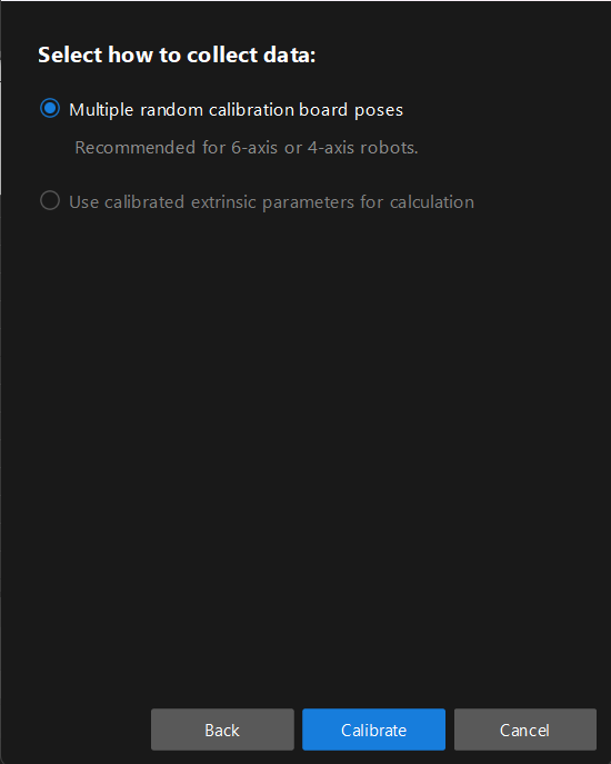
In the Select how to collect data window, select the Multiple random calibration board poses radio button.
Calibration Procedure
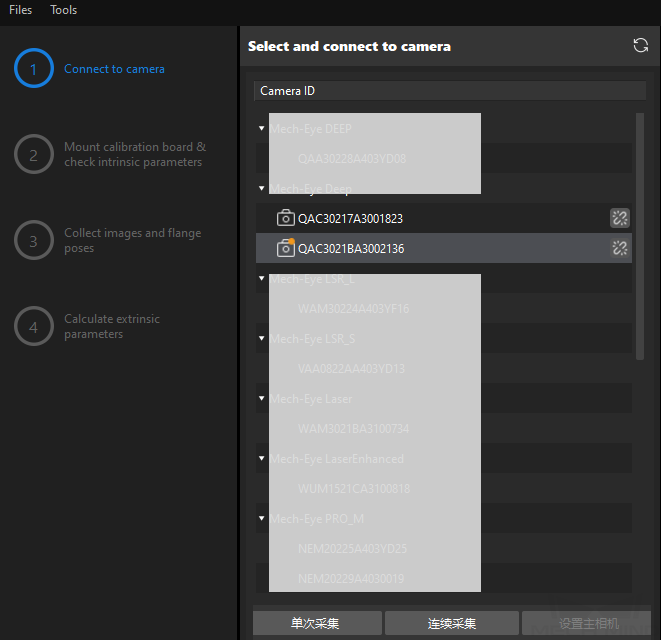
Connect to Camera
-
In the Connect to camera step, select the camera to connect in the Detected cameras list, and then click the
button or double-click the camera entry to connect to it.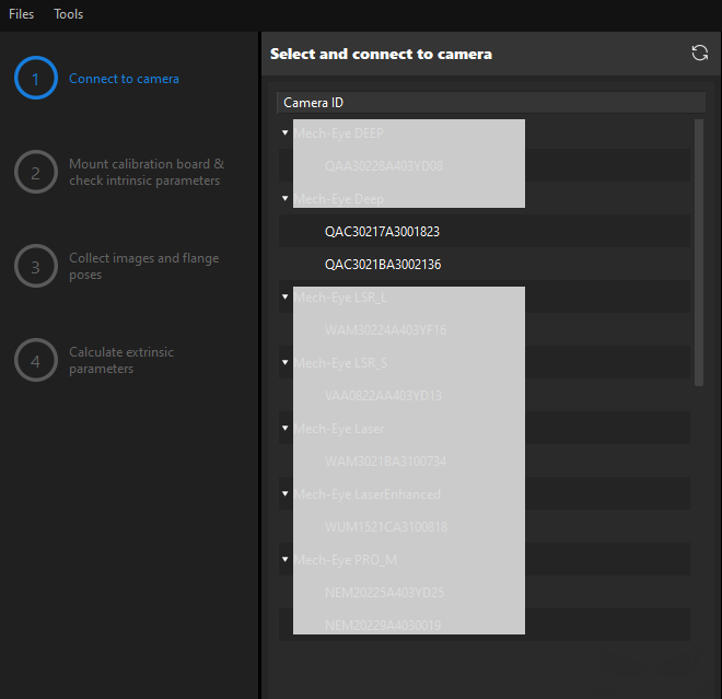
-
Repeat the preceding step to connect to the primary camera. After the primary camera is connected, the
 icon will be displayed before the camera ID.
To switch the primary camera, select a camera, and then click the Set as main button.
-
After the camera is connected, click the Acquire continuously or Acquire once button.
-
In the Image viewer panel, ensure that the camera can capture images normally and click the Next button on the bottom bar.
In this step, the 2D image and depth map are captured only for the primary camera. To confirm the effects of the images captured by the secondary camera, you can switch it to the primary camera, and switch the original primary camera back to the primary camera after confirming.
Other Steps
If the robot supports the Standard Interface or Master-Control communication mode, please complete remaining steps of the calibration procedure according to the section Calibration Procedure for automatic calibration in the ETH setup.
If the robot does not support Standard Interface or Master-Control communication mode, please complete remaining steps of the calibration procedure according to the section Calibration Procedure for manual calibration using the multiple random calibration board poses method in the ETH setup.
|
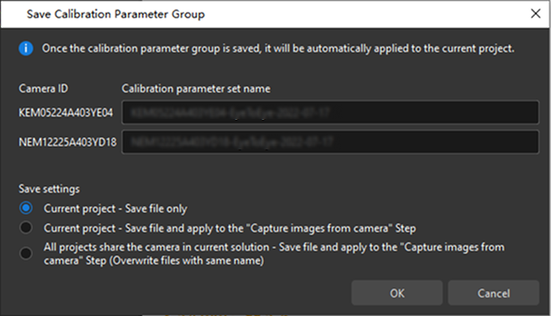
Apply Calibration Result
After calculating the extrinsic parameters, you can apply the calibration result.
Navigate to the Calculate extrinsic parameter step, click Save at the bottom. Then configure the save settings in the Save Calibration Parameter Group dialogue box, and click OK. The calibration result will be automatically saved in the “calibration” directory of the project.
|
After “Current project - Save file only” is selected, when you want to apply a new calibration parameter group later, navigate to the Step Parameters panel of the “Capture Images from Camera” Step, click the If you want the calibration parameter group to be automatically applied to the “Capture Images from Camera” Step in the project after the parameter group is saved, select the following saving method according to the actual requirement:
|
Till now, the calibration process is completed.
Check the Fusion Effect of the Calibration in the ETE Setup Using a Mech-Vision Project
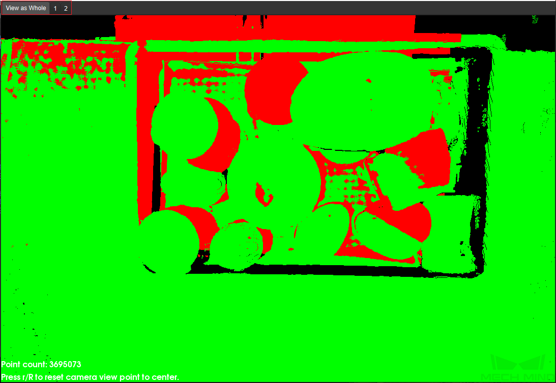
You can build a project as shown in the following figure. Note that the “Trigger Control Flow Given No Output” and “Trigger Control Flow Given Output” options in Execution Flags area should be selected.
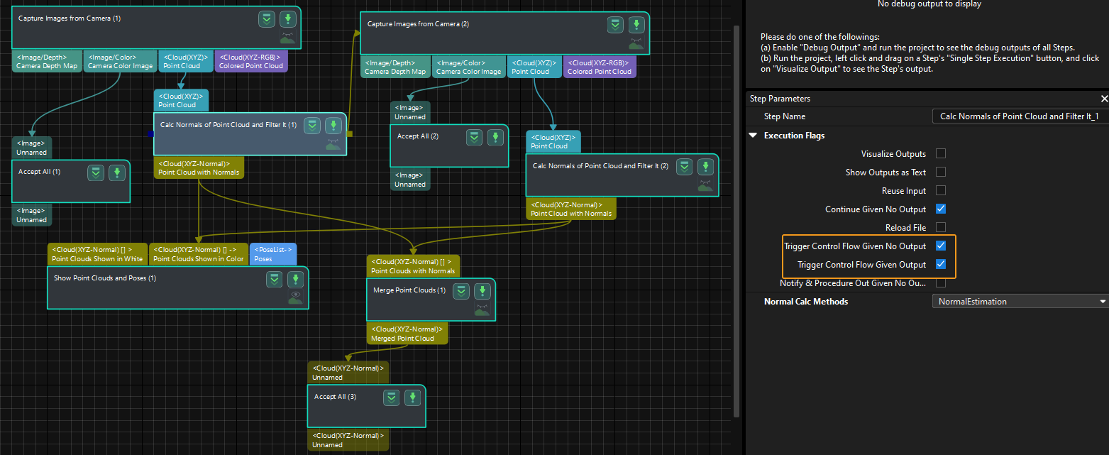
Execute the single Step “Merge Point Clouds” to display the fused point cloud. The point cloud output after merging is the fused whole point cloud, as shown in the figure below. You can click the upper left corner View as Whole| 1 | 2 to switch point clouds.