Placement Correction (Non-Fixed Placement Target)
This section introduces the target object recognition configuration workflow for non-fixed placement targets. This method is suitable for scenarios where the actual position or orientation of the placement target varies between runs, requiring visual recognition before assembly to obtain its current pose for high-precision correction.
Click Config wizard, select the Placement Correction scenario, and select the Non-fixed placement target method to enter this configuration workflow.
Usage Workflow
The overall recognition workflow includes four steps:

-
Image preprocessing: Perform color conversion, enhancement, denoising, morphological transformations, and other preprocessing on the input image to improve image quality, highlight target object features, and reduce background interference, providing a reliable data foundation for subsequent target object recognition.
-
Target object recognition: Set the region of interest and adjust recognition parameters through 2D template matching for accurate target object recognition.
-
Target object pose calculation: Combine the 2D camera’s extrinsic calibration data, the taught data of the reference target object (i.e., the target object used for teaching), and the placement target information to automatically convert the recognized 2D pose of the target object into the 3D pose required for robot placement in the robot frame, enabling high-precision correction during placement.
-
General settings: Configure pose filtering rules and output ports to ensure that output results meet subsequent picking requirements.
Image Preprocessing
Before recognizing target objects, you can choose to enable Convert color space or Image preprocessing based on the input image quality, and adjust the corresponding parameters to make image features clearer, thereby improving recognition accuracy and efficiency.
Convert Color Space
Converting the image color space can transform the input image from one color space to another, for example, from BGR to grayscale, BGR to HSV, etc. Through color space conversion, image features can be better highlighted to facilitate subsequent image processing.
For detailed parameter description and tuning examples, please read Convert Color Space.
Image Preprocessing
In image preprocessing, you can perform enhancement, denoising, morphological transformations, grayscale inversion, edge extraction, and other preprocessing operations on the input image.
For detailed parameter description and tuning examples, please read Image Preprocessing.
Target Object Recognition
After completing image preprocessing, configure the recognition settings, including setting the recognition region of interest and adjusting template matching parameters for accurate target object recognition.
Add Recognition Parameter Group
After entering the target object recognition workflow, the system will create a default recognition parameter group for managing the current recognition region of interest and related parameters.
-
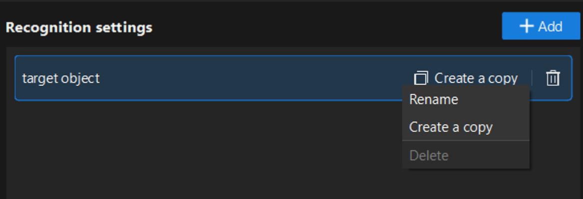
Management operations: Right-click the parameter group name, or directly click the function buttons on the right side of the parameter group to perform operations such as rename, delete, or create a copy.
-
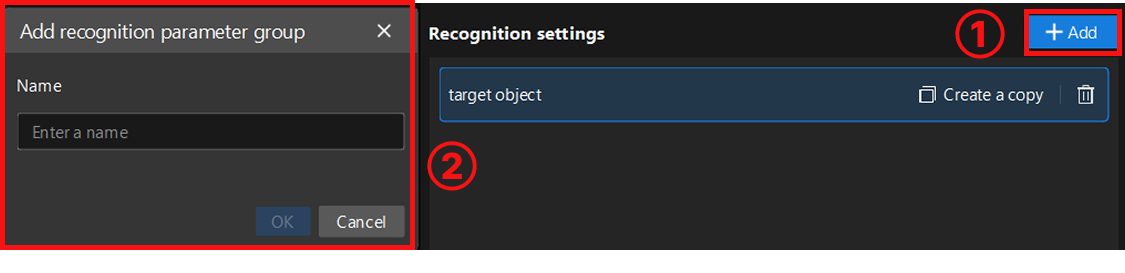
Create new parameter group: To configure a new parameter group, click the Add button in the upper-right corner to create a new parameter group. Each parameter group can independently set recognition regions and parameters without affecting each other.
Set Recognition Region
When setting the recognition region, you can choose Set all as recognition region or Customize recognition region based on actual requirements. After selecting customize, you need to click the "Select" button to manually select the recognition region. When selecting, ensure the recognition target is within the selected range.
-
Set all as recognition region: Recognizes the entire image, typically suitable for scenarios where recognition targets are widely distributed.
-
Customize recognition region: Recognizes only the selected area, typically suitable for scenarios where you only need to focus on a specific part of the image, or want to exclude irrelevant areas (such as background, fixtures, and other interferences), helping to improve recognition efficiency and accuracy.
Recognize Target Object
Set Target Object Template
After setting the recognition region, select or edit the target object template for subsequent target object recognition. Click the Edit button to enter the 2D Matching Template Editor.
Select representative and stable edge features from the image to generate the template, so that the system can subsequently search the image automatically and accurately locate target objects that match the template features, while ensuring the uniqueness and stability of matching results. For detailed instructions, please refer to 2D Matching Template Editor.
| After each template editing, click Update to apply the latest configuration. |
Adjust Recognition Parameters
After selecting the template, click Run Step to view the template matching results and recognition performance.
If the recognition performance is not satisfactory, you can adjust other parameters based on the actual features and recognition requirements of the target object for optimization.
For detailed parameter description, please read 2D Matching.
Then, click Next to proceed to the target object pose calculation workflow.
Target Object Pose Calculation
This workflow acquires reference data through teaching operations, establishing the correspondence between visual recognition and robot placement poses. During runtime, based on real-time recognition results and reference data, the system automatically calculates and corrects the placement deviation of the target object, ensuring precise placement at the non-fixed placement target.
Teaching Instruction in ETH Scenario
Operation Workflow
-
Control the robot to pick up the reference target object and move to the image-capturing point for image capture and recognition. Keep the target object position unchanged throughout the entire teaching process.
-
Click the Acquire button to obtain the currently recognized reference target object 2D pose at the image-capturing point.
-
Click the Edit button to enter the robot flange pose when picking the reference target object at the image-capturing point. This flange pose is read from the teach pendant in the robot reference frame.
-
Use the teach pendant to control the robot to reach the placement target. When the placement target is non-fixed, enter the reference placement target pose, real-time placement target pose, and the robot flange pose when placing the reference target object at the placement target. This flange pose is read from the teach pendant in the robot reference frame.
-
After completion, use the teach pendant to control the robot to move away from the placement target.
Parameter Description
| Parameter | Description |
|---|---|
Select camera Step |
Parameter description: This parameter is used to select the 2D camera Step that has completed extrinsic parameter calibration, to ensure the calibration data is correctly applied to the current Step. |
Reference target object 2D pose |
Parameter description: The 2D pose of the reference target object recognized during image capture. |
Reference pose for picking |
Parameter description: The flange pose when the robot picks the reference object during image capture. This pose is the flange pose in the robot reference frame read from the teach pendant. |
Reference placement target pose |
Parameter description: The pose of the robot in the robot reference frame under the standard placement conditions. It is usually obtained from the initial recognition result of the placement target recognition project and is used as the reference placement target pose during subsequent production processes. |
Real-time placement target pose |
Parameter description: The real-time pose of the placement target in the robot reference frame during production. When the position of the placement target shifts or changes, the placement target recognition project outputs the currently recognized placement target pose in real time. This pose can be obtained by associating a global variable. |
Reference pose for placement |
Parameter description: The robot flange pose when placing the reference target object at the placement target. This flange pose is read from the teach pendant in the robot reference frame. |
After completing the target object pose calculation, click Next to proceed to the general settings workflow.
General Settings
In this workflow, you can configure auxiliary functions beyond visual recognition, including setting pose filtering rules and configuring output ports.
Set Pose Filtering Rules
Based on actual requirements and the pose data in the Recognition result, you can set the upper and lower limits in the X, Y, and Rz directions to perform error-proofing filtering on the output target object poses. This mechanism is used to eliminate poses that may cause collisions or are not executable by the robot, ensuring that the output results are safe and usable.
Click Run Step or Run project to view the filtering status.
Configure Output Port
Here, you can select the output ports based on the actual situation of the target object. By default, the target object name and recognition pose are output.
-
Matching score: Outputs the matching score list, used to evaluate the quality of matching results.
After checking the port, the 2D Target Object Recognition Step will add the corresponding output port in real time.