Import STEP File to Generate Point Cloud Model and Configure the Trajectory
In this workflow, you can import an STEP file to generate a point cloud model and create a target object quickly.
Under the Import STEP file workflow in the target object editor, click Select, and set the target object name and the path of the STEP file to enter the configuration process. The overall configuration process is shown in the figure below.
|
If the STEP file is too large or model features are too complex, import may take a long time. It is recommended to use graphics software to remove unnecessary features in advance and keep the file size under 100 MB. |

-
Configure STL file: The imported STEP file is converted to STL. Set the unit, point cloud generation mode, and other parameters for the STL file to generate the point cloud model.
-
Edit model: Edit the generated point cloud model, including the calibration of the object center point and configuration of the point cloud model, to ensure better performance of the subsequent 3D matching.
-
Set trajectory: Create and adjust trajectories on the edited point cloud model.
-
Set collision model (optional): Generate the collision model for collision detection during trajectory planning.
The following sections provide detailed instructions on the configuration.
Configure STL File
After the imported STEP file is converted to an STL file, you need to configure the STL file to generate the point cloud model.
Select STEP File (Optional)
If you select a wrong STEP file or find the normals of the imported STL model are incorrect, click the Select file button to import another STEP file.
|
Please refer to STL Model Correction to determine whether the normals of an STL model are correct and how to fix the STL model. |
Set Unit
To fit the generated point cloud model to the actual dimensions of the target object, you need to set the dimensional unit for the STL model to either millimeters (mm) or meters (m), according to actual needs.
Select Edge Point Cloud Generation Mode
The tool provides two methods for edge point cloud acquisition. Select Generate point cloud automatically or Pick edge point cloud according to actual needs.
-
Auto generate point cloud
After this method is selected, the tool automatically generates face point cloud and all edge point clouds. This method is efficient, but may generate edge point clouds that are less meaningful for subsequent matching and reduce matching efficiency.
-
Pick edge
After this method is selected, the tool automatically generates face point cloud and generates edge point clouds through manual picking. This method can exclude meaningless or interfering edges and helps improve matching accuracy and stability.
To manually pick edge point cloud, do as follows.
-
Click Start picking to enter the "Edge picking" page.
-
Left-click at object edges to pick edges.
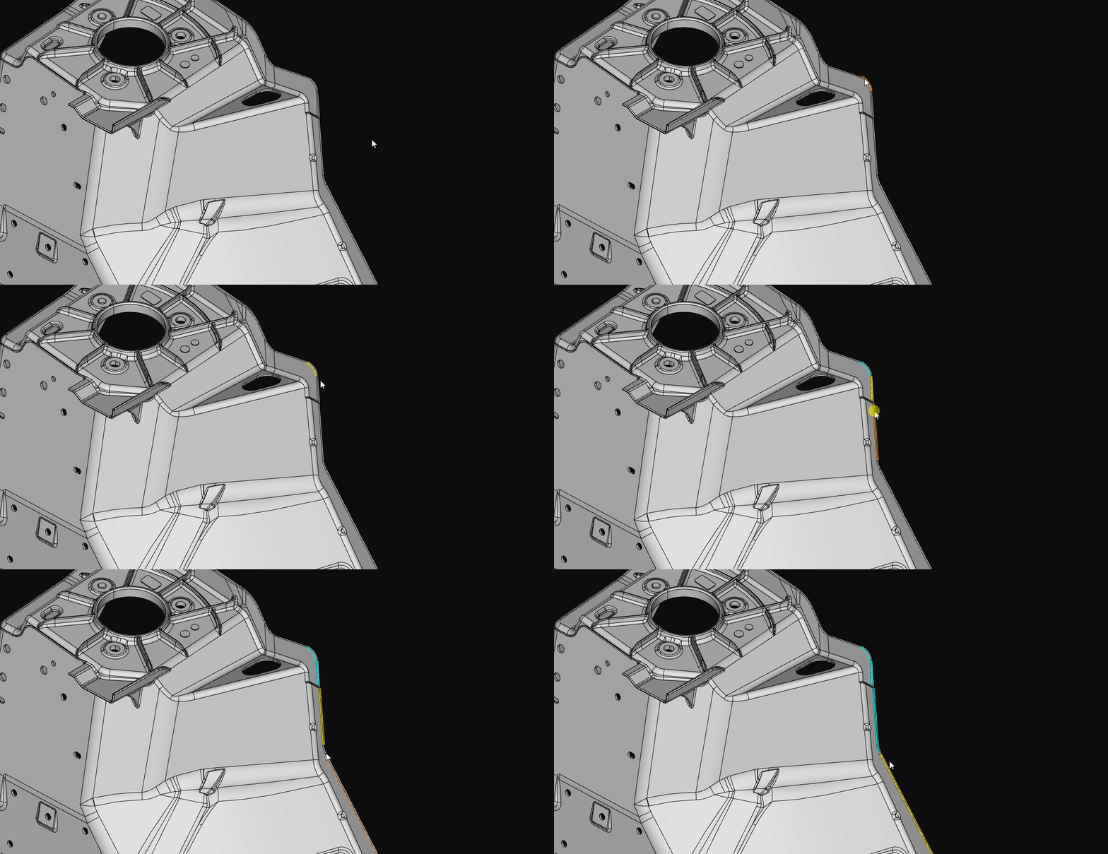
If you need to automatically pick multiple continuous edges, enable the "Auto-chain when picking edge" feature.
-
Click Save and apply to save the picking result.
-
Select the Point Cloud Generation Mode
Refer to the table below to select an appropriate point cloud generation mode based on actual requirements.
| Point cloud generation mode | Description | Effect |
|---|---|---|
Generate from entire surface |
The software generates a point cloud according to the entire surface information of the STL model.
|
|
Generate from specified views |
The software will generate point clouds from one or more selected views of the STL model and then stitch them together.
|
|
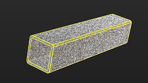
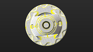
|
In some scenarios, using the point cloud generated from the entire surface for model matching can yield better results. If the matching result based on the point cloud from a specified view is unsatisfactory, it is recommended to try using the entire surface point cloud instead. |
Set Model Downsampling Method
To ensure the density and uniform distribution of the point cloud and to maintain the matching speed, the point cloud needs to be downsampled before generating a point cloud model. In general, it is recommended to select Automatic downsampling.
If the downsampling result does not meet the requirements, select Custom downsampling and set the Sampling interval based on actual conditions. The larger the Sampling interval, the sparser the downsampled point cloud; the smaller the Sampling interval, the denser the downsampled point cloud.
|
For large target objects (such as air conditioner housings), it is recommended to use Custom downsampling to prevent the loss of some feature point clouds caused by automatic downsampling. |
Now, the configuration for the STL file is finished. Click Next to edit the generated point cloud model.
Edit Point Cloud Model
The generated point cloud model should be edited for better performance in the subsequent 3D matching.
|
The process of converting the STL model to a point cloud may introduce errors, causing the point cloud model to be misaligned with the STL model. |
Edit Point Cloud
Remove Interference Point Cloud
If there are interference points around the point cloud model, you can remove the interference points by editing the point cloud. Refer to Edit Point Cloud for detailed instructions.
Select Feature Point Cloud
-
When making the edge point cloud model
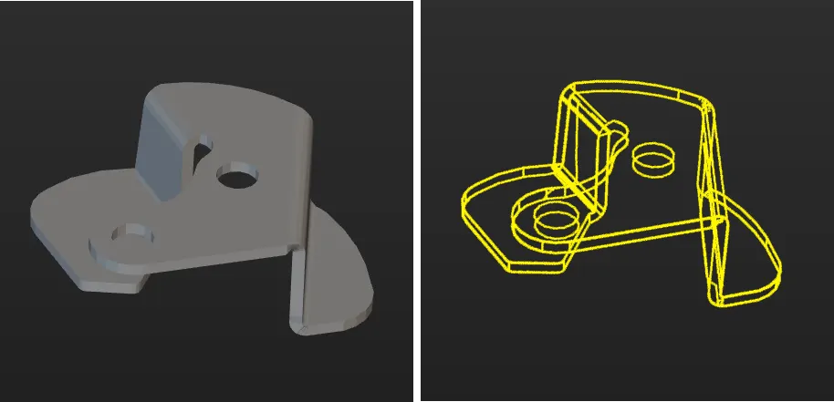
In applications, the target objects usually come in various poses, corresponding to different point clouds. Only the point cloud most representative of the edge feature of the target object should be extracted and retained in the point cloud model.
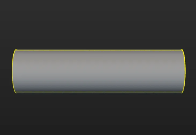
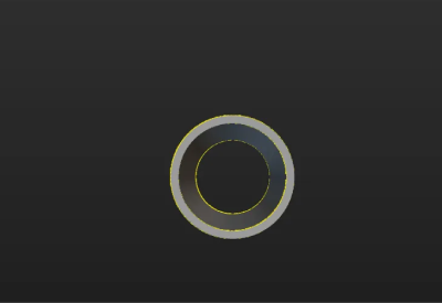
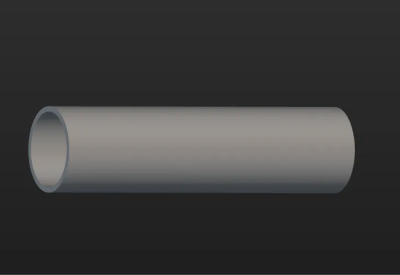
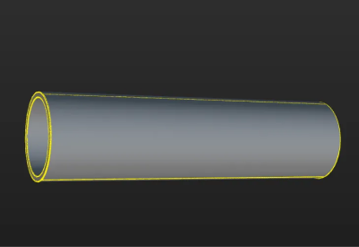
The figure below shows the edge point cloud model of the tube. The tube is symmetrical and similar to a cylinder. On the lateral area of the cylinder, only the point cloud of the edges is retained. Meanwhile, to ensure accurate positioning of the ends of the tube, the point cloud of the edges of the two ends of the tube is retained.
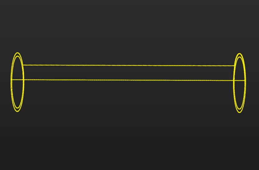
The table below shows the edge point clouds of the tube at different poses.
Tube poses Edge point clouds (in yellow) 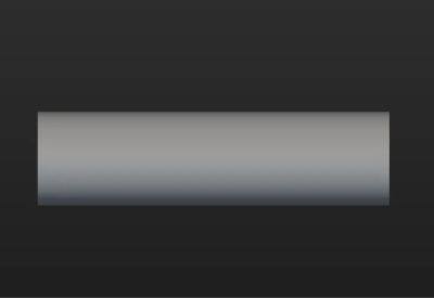

If the target object (such as a sheet metal part) is asymmetrical, the edge point clouds from all viewing angles should be retained.
-
When making the surface point cloud model
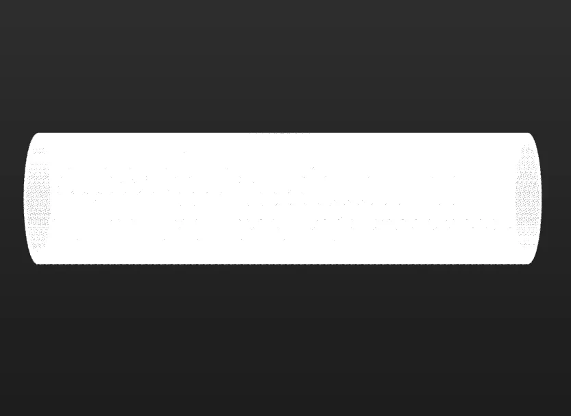
The surface point cloud model is critical in verifying the pose correctness and calculating the pose confidence. Therefore, it is recommended to use the complete surface point cloud of the target object when creating the surface point cloud model to ensure the validity. The figure below shows the surface point cloud model of the tube.
Calibrate Object Center Point
After an object center point is automatically calculated, you can calibrate it based on the actual target object in use. Select a calculation method under Calibrate center point by application, and click Start calculating to calibrate the object center point.
| Method | Description | Operation | Application Scenario |
|---|---|---|---|
Re-calculate by using original center point |
The default calculation method. Calculate the object center point according to the features of the target object and the original object center point. |
Select Re-calculate by using original center point, and click the Start calculating button. |
In general, this method can be used to calculate the center point of all target objects. |
Calibrate to center of symmetry |
Calculate the object center point according to the target object’s symmetry.
|
Select Calibrate to center of symmetry and click the Start calculating button. |
This method can be used to calculate the object center point when filtering matching results by target object symmetry. |
Calibrate to center of feature |
Calculate the object center point according to the selected Feature type and the set 3D ROI. |
|
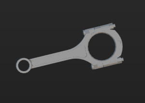
Target objects with obvious geometric features
|
Reset to Original Point Cloud
During editing, if the current point cloud result is unsatisfactory, click the [Reset button to undo all editing operations and restore the point cloud to its initial state when entering the "Edit model" step.
|
After resetting the point cloud, you need to recalculate the object center point and update the point cloud model configuration. |
Configure Point Cloud Model
To better use the point cloud model in the subsequent 3D matching and enhance matching accuracy, the tool provides the following two options for configuring the point cloud model. You can enable the Configure point cloud model feature as needed.
Calculate Poses to Filter Matching Result
Once Calculate poses to filter matching result is enabled, more matching attempts will be made based on the settings to obtain matching results with higher confidence. However, more matching attempts will lead to longer processing time.
Two methods are available: Auto-calculate unlikely poses and Configure symmetry manually. In general, Auto-calculate unlikely poses is recommended. See the following for details.
| Method | Description | Operation |
|---|---|---|
Auto-calculate unlikely poses |
Poses that may cause false matches will be calculated automatically. During the calculation process, a set of candidate poses is automatically generated based on equivalent or ambiguous poses that may arise due to the target object’s rotational symmetry about the Z-axis. In subsequent matches, poses that successfully match these poses will be considered unqualified and filtered out. |
Note that the calculation results will not be automatically updated when the point cloud model is modified. If there are any modifications, please click "Calculate unlikely poses" again to update the results. |
Configure symmetry manually |
Calculate potentially mismatched poses based on the manually set parameters such as the Order of symmetry and Angle range. In subsequent matches, poses that successfully match these poses will be considered unqualified and filtered out. |
Select the symmetry axis by referring to Rotational Symmetry of Target Objects, and then set the Order of symmetry and Angle range. |
|
After the symmetry is set manually, the symmetry setting of the target object takes effect in the Coarse Matching, Fine Matching, and Extra Fine Matching (if enabled) processes in the 3D Matching Step. |
|
When this feature is enabled, you should configure the relevant parameters in the subsequent matching Steps to activate the feature. See the following for details.
|
Set Weight Template
During target object recognition, setting a weight template highlights key features of the target object, improving the accuracy of matching results. The weight template is typically used to distinguish target object orientation. The procedures to set a weight template are as follows.
|
A weight template can only be set when the Point cloud display settings is set to Display surface point cloud only. |
-
Click Edit template.
-
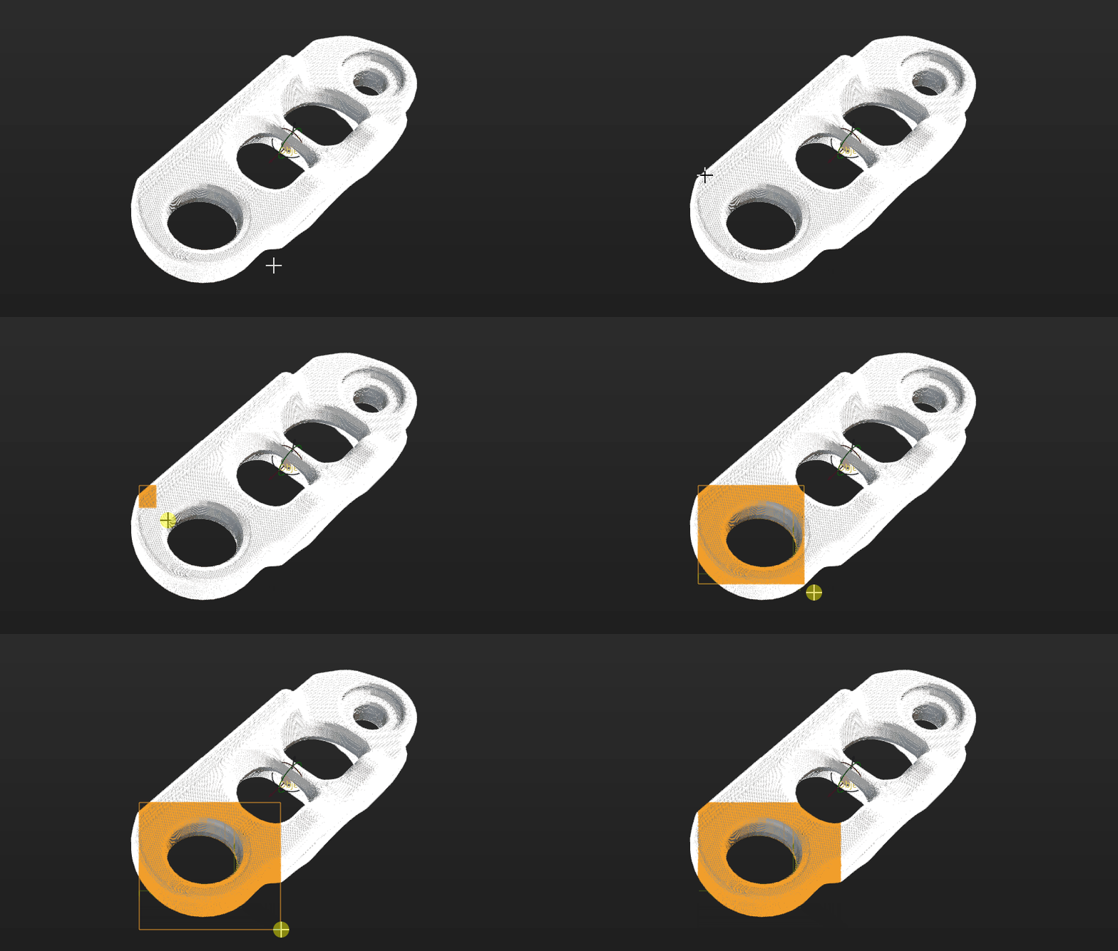
In the visualization area, hold and press the right mouse button to select a part of the features on the target object. The selected part, i.e., the weight template, will be assigned more weight in the matching process.
By holding Shift and the right mouse button together, you can set multiple weighted areas in a single point cloud model.
-
Click Apply to complete setting the weight template.
|
For the configured weight template to take effect in the subsequent matching, go to the “Model Settings” parameter of the “3D Matching” Step, and select the model with properly set weight template. Then, go to “Pose Filtering” and enable Consider Weight in Result Verification. The “Consider Weight in Result Verification” parameter will appear after the “Parameter Tuning Level” is set to Expert. |
Now the editing of the point cloud model is completed. You can click Next to set the trajectory for the point cloud model.
Set Trajectory
Create Trajectory
The tool provides two methods to create trajectories: Manual create and Automatic create.
In this workflow, Automatic create is recommended to create trajectories on the STL model.
Create Trajectory Manually
After clicking Manual create in the "Set trajectory" workflow, you can enter its page. The detailed operation steps are as follows.
-
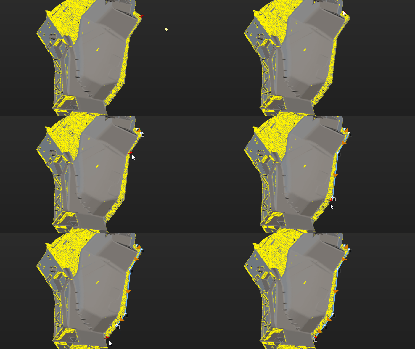
Pick trajectory points.
Hold Shift and right-click on the object to pick trajectory points. The tool automatically connects trajectory points into a trajectory.
-
Adjust trajectory points.
The list on the right side of the visualization area shows created trajectory points. If trajectory points do not meet requirements, adjust them as follows.
Operation Description Adjust trajectory point position and orientation
Select the trajectory point, then adjust corresponding values in "Trajectory point settings" to adjust its position and orientation.
Adjust trajectory point order
Drag in the list to adjust trajectory point order.
Add trajectory point
ClickAdd button, and the tool adds a new trajectory point after the last trajectory point.
Align trajectory points
Select at least three trajectory points in the list, then click Auto-align. The Z-axis of selected points becomes perpendicular to the fitted plane of these points, and the X-axis points to the next trajectory point.
Interpolate trajectory points
If picked trajectory points are unevenly distributed, interpolate trajectory points to make the distribution more uniform.
Select two trajectory points, set the "Max distance" parameter, and click Interpolate points. When the distance between the two points exceeds this value, the tool automatically inserts trajectory points between them, replacing other trajectory points between the selected points. -
Save trajectory.
After creating trajectories, click Save and apply to save trajectories.
Create Trajectory Automatically
After clicking Automatic create in the "Set trajectory" workflow, you can enter its page. The detailed operation steps are as follows.
-
Set picking rules.
Before picking trajectories, set picking rules first. Details are as follows.
-
Orientation settings
Parameter Description Illustration Tool direction
This parameter is used to set the orientation of the end tool (such as spray gun, grinding head, or glue gun) when moving along trajectories.
-
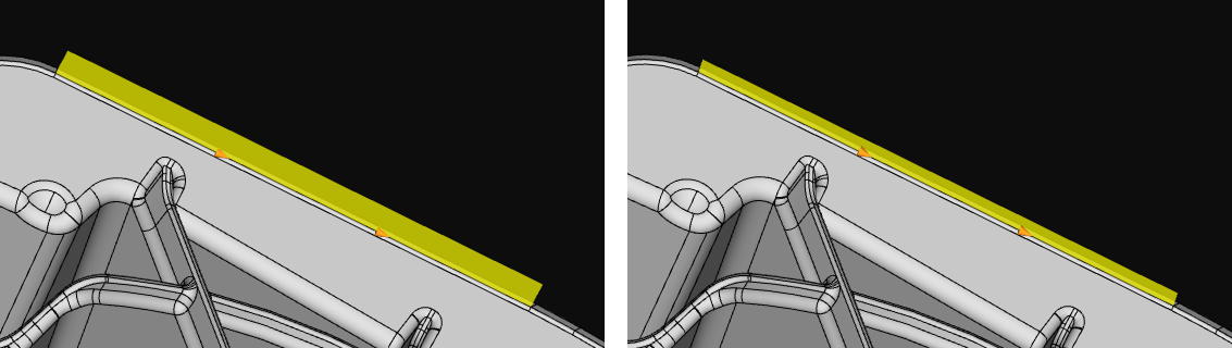
When tool direction is set to Perpendicular, the tool orientation at each trajectory point is consistent with the normal vector of the object surface at that point, as shown on the left side in the diagram. For example, the glue gun is perpendicular to the object surface.
-
When tool direction is set to Tangent, the tool orientation at each trajectory point is consistent with the tangent direction of the trajectory, as shown on the right side in the diagram. For example, the grinding head fits the object surface.
Generate opposite tool direction
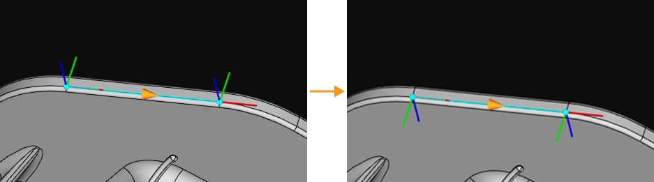
This parameter is used to reverse tool orientation. After enabled, tool orientation is reversed during trajectory picking, meaning the Z-axis direction of trajectory points is flipped. This function only changes tool orientation and does not affect trajectory point positions.
Generate opposite trajectory direction
This parameter is used to reverse trajectory direction. After enabled, trajectory direction is reversed during trajectory picking, meaning the X-axis direction of trajectory points is flipped. This function only changes trajectory direction and does not affect trajectory point positions.
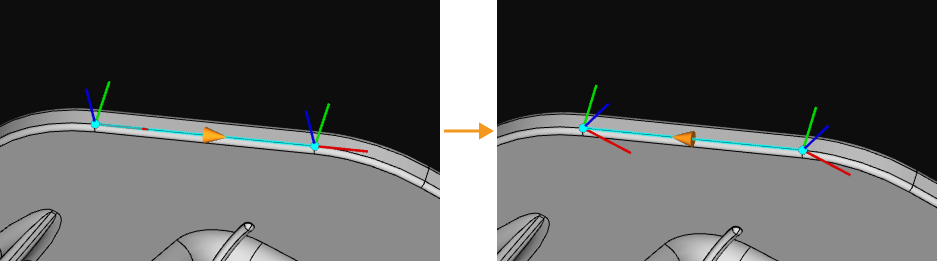
-
-
Merge settings
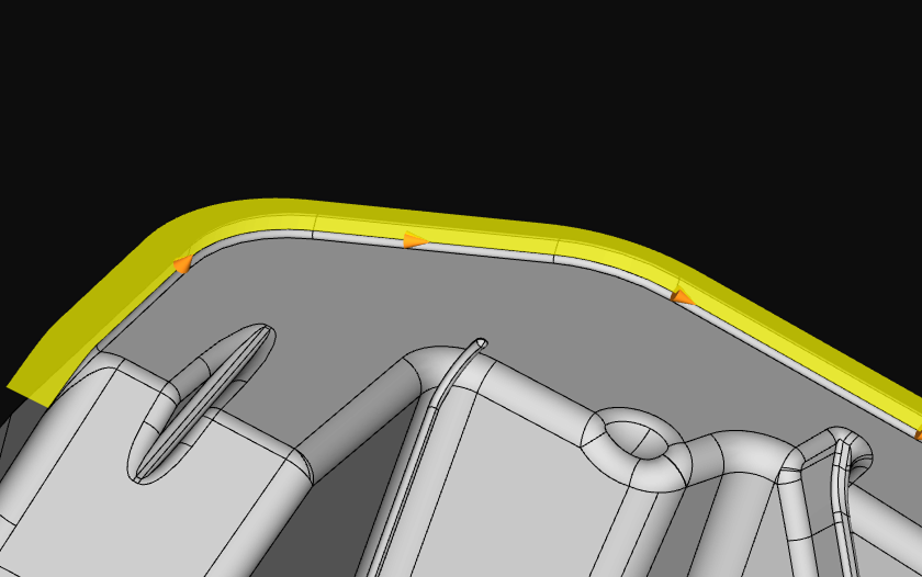
Parameter Description Illustration Auto-chain when picking trajectory
After enabled, in a single picking process, multiple adjacent trajectories can be picked continuously and automatically connected into one complete continuous trajectory. This reduces repeated operations and improves picking efficiency.
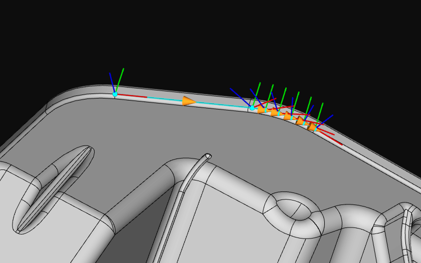
Auto-merge when picking trajectory
After enabled, when current trajectory picking is completed, the tool attempts to automatically merge the current trajectory with the previous trajectory. Trajectories are merged only when trajectory directions are consistent. If trajectory directions are inconsistent, automatic merge is not performed.
Consider tool direction when merging trajectories
This parameter is a condition for trajectory merging and should be used with "Auto-merge when picking trajectory". During trajectory picking, trajectories are merged only when both trajectory directions and tool orientations are consistent.
-
-
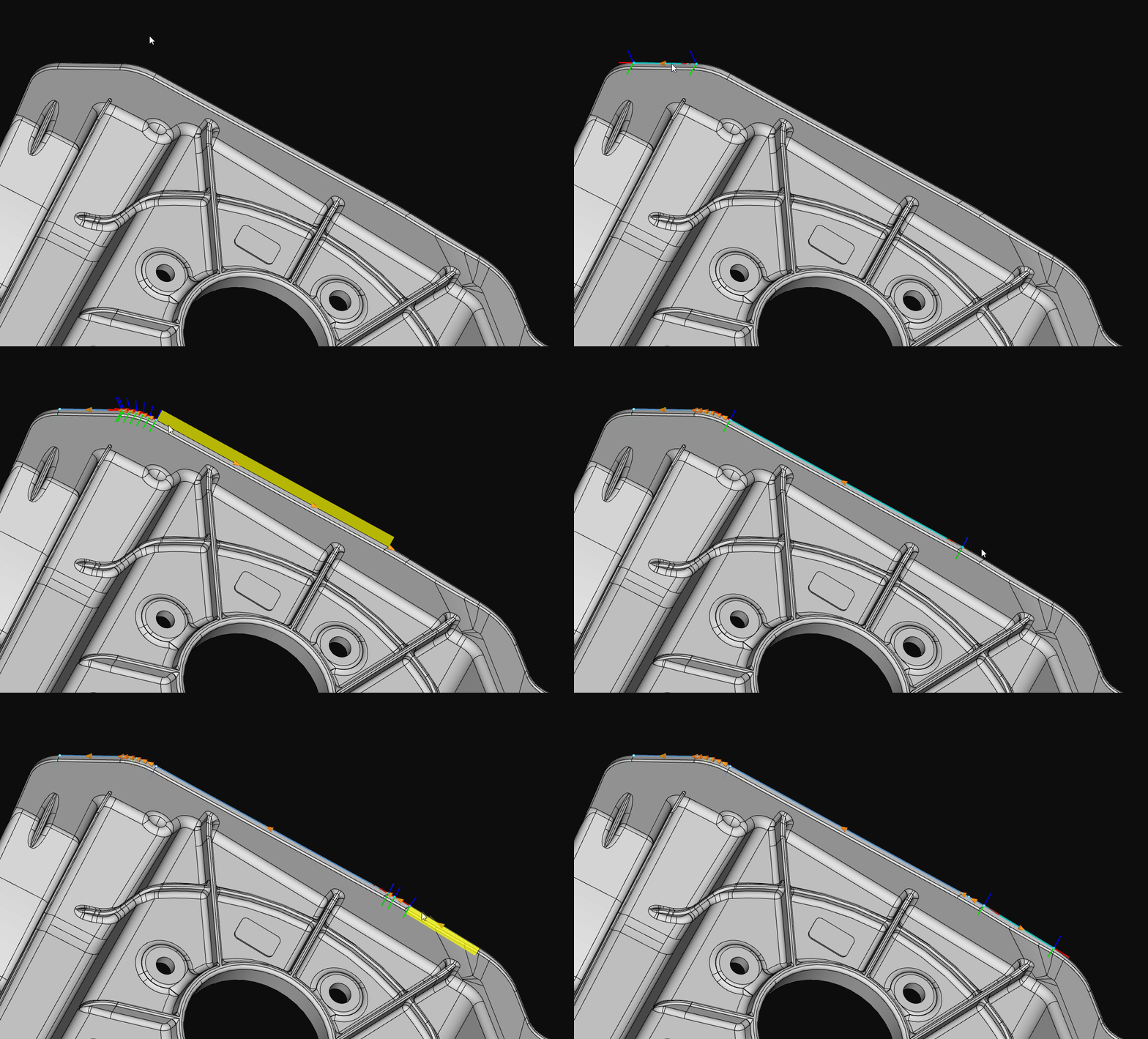
Pick trajectories.
Left-click on the object to pick trajectories.
-
Adjust trajectory points.
Picked trajectories are displayed under "Picking results". If needed, you can simplify trajectories by adjusting the following parameters. By reducing the number of trajectory points, the trajectory shape is simplified while preserving the overall shape as much as possible. This is suitable for scenarios that require reduced trajectory complexity, such as reducing subsequent processing time and improving robot motion efficiency.
Parameter Description Illustration Max deviation
Maximum allowed deviation (H) when simplifying trajectories. The larger the value, the more points are reduced, but the trajectory shape may be distorted.
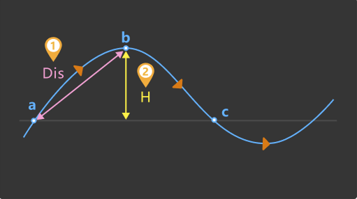
Min distance to retain
If the distance (Dis) between two trajectory points in the original trajectory is greater than this value, both points will be retained.
-
Save trajectory.
After creating trajectories, click Save and apply to save trajectories.
Adjust Trajectory
After trajectories are created, you can adjust trajectories.
-
Adjust trajectory line
After creating trajectories, if you need to offset a trajectory line by a certain distance along the Z-axis to better meet actual trajectory operation requirements, select a trajectory line in the trajectory list and set the Z-axis offset distance parameter.
-
Adjust trajectory point individually
After selecting a trajectory point in the trajectory list, adjust corresponding values in the parameter settings area to adjust its position and orientation.
|
For other operations on trajectory adjustment, refer to Adjust Trajectory. |
Preview End Tool
After trajectories are created, you can preview the positional relationship between the end tool and trajectories by following these steps.
-
Ensure the Mech-Viz project is within the current solution.
To ensure that the end tool information in Mech-Viz can be updated in the target object editor, refer to xref:viz-operation-guide:project-and-solution.adoc#export-project-to-solution[Mech-VizExport ProjectMech-Viz to Solution to move the project to the current solution.
-
Add an end tool.
Add an end tool and set the TCP in Mech-Viz.
-
Preview and enable the tool.
Once the end tool is added, the tool information will be automatically updated in the tool list within the target object editor. You can select a tool in the tool list according to actual needs, preview the positional relationship between trajectories and tools in actual trajectory operations in the visualization area (as shown below), or enable the end tool for actual trajectory operations.
If you have modified the tool configurations in Mech-Viz, save the changes in Mech-Viz to update the tool list in the target object editor. In addition, enabling the corresponding tool for the trajectory in the target object editor is a prerequisite for successful simulation in Mech-Viz. 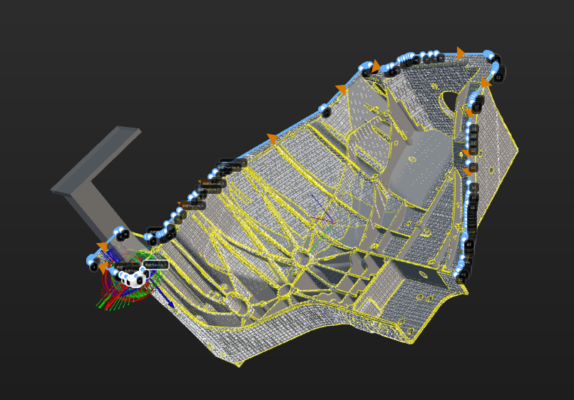
Set Collision Model (Optional)
The collision model is a 3D virtual object used in collision detection for path planning. You can configure the following settings on the collision model according to the actual situation.
Set Collision Model
The tool automatically recommends the collision model generating mode based on the current configuration workflow. The recommended mode for this case is Use STL model to generate point cloud cube. This tool will generate the point cloud cube based on the imported STL model and conduct collision detection. The collision model generated in this method features high accuracy, while the collision detection speed is lower.
You can use the "Display collision model" feature to preview the generated collision model.
Configure Symmetry of Held Target Object
Rotational symmetry is the property of the target object that allows it to coincide with itself after rotating a certain angle around its axis of symmetry. When the “Waypoint type” is “Target object pose,” configuring the rotational symmetry can prevent the robot’s tool from unnecessary rotations while handling the target object. This increases the success rate of path planning and reduces the time required for path planning, allowing the robot to move more smoothly and swiftly.
Select the symmetry axis by referring to Rotational Symmetry of Target Objects, and then set the Order of symmetry and Angle range.
Now, the collision model settings are completed. Click Save to save the target object to Solution folder\resource\workobject_library. Then the target object can be used in subsequent 3D matching Steps.