Error-Proofing Check (Binary Classification)
This section introduces the target object recognition configuration workflow for the binary classification scenario. This method is used to determine whether the front-back orientation of a target object is correct, or whether a target object is present, preventing missed assembly, reversed assembly, and other errors.
Click Config wizard, select the Error-Proofing Check scenario, and select the Binary classification method to enter this configuration workflow.
Usage Workflow
The overall recognition workflow includes four steps:

-
Image preprocessing: Perform color conversion, enhancement, denoising, morphological transformations, and other preprocessing on the input image to improve image quality, highlight target object features, and reduce background interference, providing a reliable data foundation for subsequent target object recognition.
-
Pose correction: Set the recognition region and align the recognition target with the template through alignment operations. Select an appropriate correction method based on recognition target features, flexibly configure parameters, eliminate position and angle deviations, and improve recognition accuracy and result reliability.
-
Error-proofing check: Based on actual requirements, set the target area for detection in the aligned image, complete image labeling and judgment rule configuration, and implement automatic recognition and classification of the target object’s front-back orientation/presence status.
-
General settings: Configure output ports to output judgment results, status, and other related information, meeting production line automated detection requirements.
Image Preprocessing
Before recognizing target objects, you can choose to enable Convert color space or Image preprocessing based on the input image quality, and adjust the corresponding parameters to make image features clearer, thereby improving recognition accuracy and efficiency.
Convert Color Space
Converting the image color space can transform the input image from one color space to another, for example, from BGR to grayscale, BGR to HSV, etc. Through color space conversion, image features can be better highlighted to facilitate subsequent image processing.
For detailed parameter description and tuning examples, please read Convert Color Space.
Image Preprocessing
In image preprocessing, you can perform enhancement, denoising, morphological transformations, grayscale inversion, edge extraction, and other preprocessing operations on the input image.
For detailed parameter description and tuning examples, please read Image Preprocessing.
Pose Correction
After completing image preprocessing, configure the pose correction settings. By setting the recognition region and correction parameters, the pose of the recognition target in the current image is corrected to align with the template, ensuring the accuracy and reliability of subsequent recognition.
Add Correction Settings
After entering the pose correction workflow, you need to create a new correction parameter group. The system supports creating multiple parameter groups, each of which can independently set recognition regions and parameters without affecting each other.
Click the Add button to enter the new parameter group window. When creating a parameter group, select an appropriate correction method based on image features and configure the corresponding parameters.
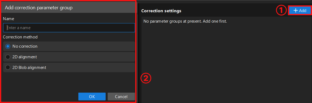
Currently, the following three correction methods are supported:
-
No correction: Uses the original input image directly for recognition without any pose correction processing. Suitable for scenarios where the recognition target position is relatively fixed in the image and the correction accuracy requirement is not high.
-
2D alignment: Aligns the recognition target’s pose with the template through translation and rotation operations. This method can extract the edge contour of the recognition target and uses an edge matching algorithm for precise alignment. Suitable for scenarios where the recognition target position is not fixed but has distinct fixed contours. For detailed configuration, read 2D Alignment.
-
2D Blob alignment: Used to detect bright and dark regions (i.e., Blobs) in the image. Filters target Blobs based on geometric features of the Blob (such as area, centroid, etc.) and calculates its minimum bounding rotated rectangle. Then adjusts the image pose so that the target Blob’s centroid aligns with the image center point, and the principal axis of its minimum bounding rotated rectangle aligns with the image coordinate axes. For detailed configuration, read 2D Blob Alignment.
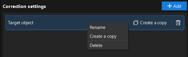
After creating the parameter group, right-click the parameter group name, or directly click the function buttons on its right side to perform operations such as rename, delete, or create a copy.
2D Alignment
2D alignment is a correction method that aligns the recognition target in the input image with the template through translation and rotation operations. It can eliminate recognition errors caused by inconsistent recognition target positions, improving recognition stability. After selecting this method, you need to complete recognition region settings, template settings, and recognition parameter tuning in sequence.
Set Target Region
Used to set the effective range for alignment. When selecting, the recognition target must be fully covered with appropriate margins on all sides to ensure the stability of alignment operations and the accuracy of subsequent recognition. You can select Set all as target region or Customize target region based on actual requirements. After selecting customize, click the "Select" button to manually select the recognition region.
-
Set all as target region: Recognizes the entire image, typically suitable for scenarios where recognition targets are widely distributed.
-
Customize target region: Recognizes only the selected area, typically suitable for scenarios where you only need to focus on a specific part of the image, or want to exclude irrelevant areas (such as background, fixtures, and other interferences), helping to improve recognition efficiency and accuracy.
Recognize Target Object
Set Target Object Template
After setting the recognition region, select or edit the template for subsequent positioning and matching of the recognition target. Click the Edit button to enter the 2D Matching Template Editor.
Select representative and stable edge features from the image to generate the template, so that the system can subsequently search the image automatically and accurately locate target objects that match the template features, while ensuring the uniqueness and stability of matching results. For detailed instructions, please refer to 2D Matching Template Editor.
| After each template editing, click Update to apply the latest configuration. |
Adjust Recognition Parameters
After selecting the template, click Run Step to view the template matching results and recognition performance.
If the recognition performance is not satisfactory, you can adjust other parameters based on the features and requirements of the recognition target for optimization.
For detailed parameter description, please refer to 2D Alignment.
Then, click Next to proceed to the error-proofing check workflow.
2D Blob Alignment
2D Blob alignment is a Blob-based correction method. This method detects all Blobs in the image and filters out the Blob with the most prominent geometric features. It then adjusts the image pose so that the target Blob’s centroid aligns with the image center point, and the principal axis of its minimum bounding rotated rectangle aligns with the image coordinate axes. After selecting 2D Blob alignment, you need to complete recognition region settings and recognition parameter tuning in sequence.
Set Target Region
Used to set the effective range for alignment. When selecting, the recognition target must be fully covered with appropriate margins on all sides to ensure the stability of alignment operations and the accuracy of subsequent recognition. You can customize the settings based on actual requirements.
The system supports rectangle and circle selection modes, and allows mixed addition of multiple regions. That is, on the same image, multiple rectangle or circle recognition regions can exist simultaneously to meet recognition requirements in complex scenarios.
Recognize Target Object
After setting the recognition region, you can adjust other parameters based on the features and requirements of the recognition target for optimization.
For detailed parameter description and tuning suggestions, please refer to 2D Blob Alignment.
You can also learn more about the usage of each parameter through tuning examples.
Error-Proofing Check
After aligning the image, enter the binary classification judgment workflow. By setting the target area, labeling images, and configuring judgment rules, implement automatic recognition and classification of the target object’s front-back orientation/presence status.
Acquire Images
Acquire image data for training the model.
-
Confirm that the input port of the current Step is connected to image data.
-
When entering the tool, the camera will automatically acquire one image for model training. You can click the Acquire images button to acquire new image data for model training.
|
When acquiring images, it is recommended to cover typical variations in the production site, including:
Diverse images help the model adapt to the actual environment and improve judgment accuracy. |
Set ROI
After acquiring images, you need to set the ROI for subsequent labeling and training.
-
Click the Edit button to enter the ROI setting interface.
-
Set the ROI.
Select the "Rectangle" or "Circle" selection tool to drag and draw the ROI in the visualization area. Please accurately select the target area based on the actual position and shape of the target object, avoiding irrelevant backgrounds.
-
When selecting the target area, you can select only the area containing key features.
-
If you need to manually select multiple ROIs, it is recommended to draw one ROI first, then generate other ROIs by copying and pasting to ensure consistent size for each target area, improving the stability of model training and judgment accuracy.
-
-
Set mask region (optional).
When there are irrelevant interferences such as reflections, shadows, or fixed backgrounds within the target area, you can set mask regions to exclude them, avoiding impact on model training and classification judgment results.
Click the Set mask region button, and use the "Polygon" selection tool to draw the mask region in the visualization area: click the left mouse button to add polygon vertices, and double-click the right mouse button to close the polygon and complete the selection.
-
After the setting is completed, click Save and apply to apply the ROI configuration.
|
When the masks of the target area and mask region completely overlap, only the topmost layer supports editing.
|
Label Images
After acquiring images and setting the ROI, you need to label the images so that the model can learn the features of different classes.
-
Click the Edit button to enter the image labeling process.
-
In the visualization area, select the target ROI that has been outlined, and in the label class options on the right, click the Label images button for the OK or NG class to complete labeling of a single target.
This tool uses fixed OK and NG classes for labeling. You can define their business meaning according to actual requirements. For example, you can label "front side" or "present" as the OK class, and "back side" or "absent" as the NG class.
-
If all targets in the current image cover both OK and NG classes, labeling can be completed directly without acquiring new images. If a class is not covered, or the image contains only a single target, click the Acquire images button to acquire new images to supplement the uncovered class, and repeat the above labeling steps. At least one image should be labeled for the OK class; if the NG class includes multiple situations, it is recommended to label at least one image for each situation to cover the typical cases of that class.
-
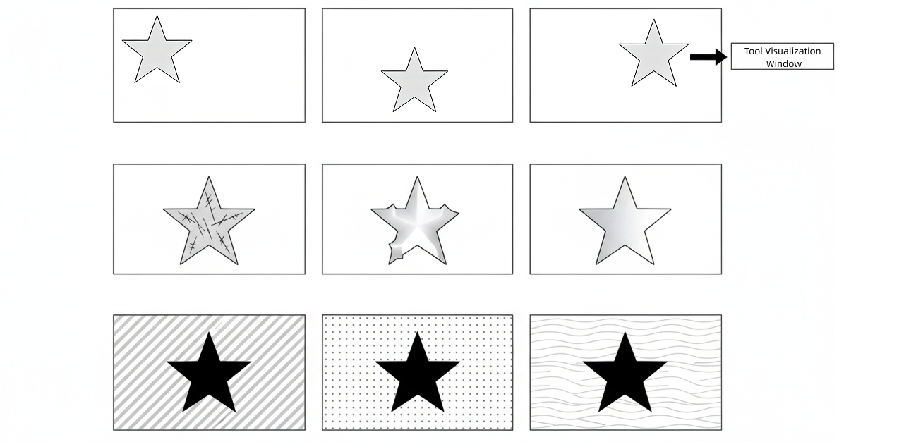
To ensure accurate model recognition, it is recommended that the training data include diverse images of both OK and NG classes of the target object, covering multiple shooting conditions (such as position offset, stains, scratches, deformation, color tone, or background differences). The more thorough the labeling, the stronger the model’s adaptability.
-
Avoid labeling images with ambiguous classes to prevent affecting the model’s learning performance.
-
If there is uncertainty in lighting or target object angles in the actual production scenario, you can enable the “Adapt to brightness changes” or “Adapt to rotation changes” options in Advanced settings. The system will automatically apply slight rotation and brightness adjustments to the labeled images to generate more virtual images under different conditions for model training, thereby helping to expand training content and improve the model’s generalization ability.
-
-
After labeling is completed, click Save and apply to save the labeling results.
Train and Validate Model
-
Train the model.
After labeling is completed, click the Train button to start model training, and wait for the training completed prompt.
-
Validate the model performance.
Click the Validate button to enter the validation interface. You can view or set the following parameters in this interface, and observe whether the model’s recognition results meet expectations.
Parameter Description Validation result
Parameter description: Displays the classification judgment result. The result is displayed as OK or NG class based on the recognition result.
Time
Parameter description: Displays the single inference time (unit: ms).
Confidence threshold
Parameter description: The minimum confidence standard for the model to judge as the OK class. Images below this value will be judged as the NG class.
Default value: 0.5
Tuning instructions: It is recommended to use the default value.Judgment settings
Parameter description: When there are multiple ROIs in the image, selecting "All OK" means the validation result is displayed as OK only when all ROIs are recognized as the OK class; selecting "At least one OK" means the validation result is displayed as OK as long as any one ROI is recognized as the OK class.
Value list: All OK, At least one OK
Default value: All OK
Tuning instructions: Please select the appropriate judgment setting according to actual requirements.Heatmap
Parameter description: When enabled, a visual heatmap of the model’s attention areas is overlaid on the image. The deeper (or warmer) the color, the higher the model’s attention to the features in that area.
Default value: Off.
Tuning instructions: Typically, the heatmap should be concentrated on feature positions within the target area, such as edges, defects, or textures. It can be used to help judge the model’s focus areas.
If the heatmap distribution is too scattered or concentrated on irrelevant areas, it may indicate that the model has not correctly learned effective features. In this case, it is recommended to go back to the previous steps to supplement more diverse training images and retrain the model.
-
Additional training (optional).
If the judgment results do not meet expectations, you can use the "Additional training" function to supplement images that were incorrectly recognized or not covered during validation.
-
Click Additional training to enter the image labeling process.
-
In the visualization area, select incorrectly judged images or re-acquire images for labeling.
-
After labeling is completed, click Save and apply, and the system will re-execute training and validation based on the new labeling data.
-
You can repeat the "Train → Validate → Additional training" cycle until the model performance meets expectations.
Additional training is incremental training that optimizes on the existing model basis without starting from scratch.
If the performance does not improve after additional training, it is recommended to check the labeling accuracy, or return to the acquisition stage to supplement more typical images.
-
-
Save and apply the model.
After validation is passed, click the Save and apply button to save the model configuration.
At this point, the model configuration is completed. Click Next to proceed to the general settings workflow.
General Settings
In this workflow, you can configure auxiliary functions beyond visual recognition. Currently, output port configuration is supported.
Configure Output Port
Here, you can select the output ports based on actual requirements. By default, the classification judgment result is output, i.e., OK or NG.
-
Classification status: Used to indicate whether classification is successful; true for success, false for failure.
-
Classification confidence: Outputs the confidence for each classification result.
-
Image with result: Outputs an image with detection results.
After checking the relevant ports, the 2D Target Object Recognition Step will add the corresponding output ports in real time.