Pose Correction for Assembly
This topic introduces the "Pose Correction for Assembly" function in the "Advanced Pose Transformation" Step and its usage procedure.
Introduction
This function is used to automatically correct the TCP pose or flange pose during assembly based on the result of a second image capture, after the robot has picked a target object and before executing the assembly. It can compensate for picking errors or placement position deviations, improving the precision of robot assembly. Both 3D and 2D cameras are supported for the second image capture, and it is applicable to both fixed and non-fixed placement target assembly scenarios.
Prerequisites and Constraints
Before using the "Pose Correction for Assembly" function, ensure the following prerequisites and constraints are met.
-
Reference frame constraints
All pose data input to Transform Poses (Advanced) must be poses in the robot reference frame. If the input poses are from model matching, they need to be preprocessed according to their types:
-
3D poses: Generated by Steps such as "3D Matching". These are typically 3D poses in the camera reference frame and need to be transformed to the robot frame using the Transform Poses Step.
-
2D poses: Generated by Steps such as "2D Matching". These are typically 2D poses in the camera reference frame and need to be converted to 3D poses in the robot frame using the "Convert 2D Point to 3D Pose" Step.
-
-
Tool configuration (TCP) requirements
The same tool configuration (TCP) must be used during both the teaching phase and the actual running phase. If the gripper is replaced or the TCP is adjusted, the relevant teaching process must be repeated to ensure consistency of the pose relationships.
-
Secondary image capture requirements
Pose correction relies on a secondary image capture performed at a fixed image-capturing point after the robot picks the target object. The pose input requirements differ depending on the camera type:
-
3D camera scene: the TCP pose recorded at the moment of the second image capture during the teaching phase is required. This pose serves as the reference baseline for the "ideal pick state" and is used together with the real-time target object pose identified during operation to calculate the pick deviation and correct the assembly pose.
-
2D camera scenario: The flange pose recorded at the moment of the second image capture during the teaching phase is required. This pose serves as the reference baseline for the "ideal pick state" and is used together with the real-time target object pose identified during operation to calculate the pick deviation and correct the assembly pose.
-
-
Placement type description
-
Fixed placement target: The position and orientation of the placement target remain unchanged during the running phase. Its ideal assembly state is defined only during the teaching phase and does not require real-time identification during the running phase.
-
Non-fixed placement target: The actual position or orientation of the placement target cannot be predetermined for each run and may deviate or change. The current pose of the placement target must be obtained in real-time through placement target recognition before assembly.
-
Usage Procedure
This section introduces the assembly pose correction methods for the following four assembly scenarios. Users can select the appropriate procedure based on actual requirements:
Correct Assembly Pose at a Fixed Placement Target Using a 3D Camera
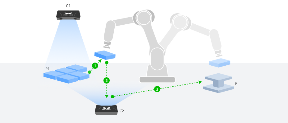
After the robot picks a target object, it moves to a fixed image-capturing point where a 3D camera captures the point cloud of the target object and calculates the actual pose. Combined with the taught fixed placement target pose, the corrected assembly TCP pose is calculated.
|
The following uses two 3D cameras with ETH mounting as an example: Camera C1 is used for the initial positioning and picking of the target object, and Camera C2 performs the second image capture of the picked target object at a fixed image-capturing point. The assembly TCP pose correction process is described below. Other camera types or mounting methods can refer to this process and adapt based on actual conditions. |
Configure Step Ports
-
Click the Config wizard1 button to open the pose transformation tool and select Pose correction for assembly.
-
In the parameter panel on the right, select the assembly scenario by setting the camera type to 3D camera and the placement type to Fixed placement target.
-
Click the OK button to complete the configuration.
The input and output ports after configuration are as follows:
Input
| Input port | Data type | Description |
|---|---|---|
TCP at Capture |
Pose [] |
The TCP recorded during teaching when the robot, after picking up the target object, moves to the secondary image-capturing point to acquire an image of the target object. This TCP value is read from the teach pendant in the robot frame. |
Target Object Pose at Capture |
Pose [] |
The real-time pose of the picked target object in the robot frame during the second image capture. |
Fixed Placement Target Pose |
Pose [] |
The TCP recorded during teaching when the robot is jogged to move the target object to its designated placing point for assembly. |
Output
| Output port | Data type | Description |
|---|---|---|
Assembly Pose |
Pose [] |
The corrected assembly pose obtained by applying a rotational transformation to the input taught TCP pose and combining it with other input poses. This output pose can be directly fed into the "Output" Step. |
Record Taught Poses (Teaching Phase)
Before running the Step, a complete teaching process using a standard target object and a reference placement position is required to collect the following data.
-
Record the fixed placement target pose.
Use the teach pendant to control the robot to pick a standard target object and move it to the ideal assembly pose, ensuring that the target object P1 is fully aligned with the placement position P. The gripper must remain closed and the target object must remain picked throughout the process. After the robot comes to a stop, record the robot TCP pose at this point as the "Fixed Placement Target Pose".
-
Record the TCP at capture and create the target object point cloud model.
-
While the target object remains picked, use the teach pendant to move the target object to an appropriate secondary image-capturing point, ensuring Camera C2 can capture the target object features completely and clearly. Set this as the fixed image-capturing point and record the TCP pose at this point as the "TCP at Capture". This pose will be used for creating the target object point cloud model and will serve as the reference baseline for pose correction.
-
At the current image-capturing point, trigger Camera C2 to capture the target object point cloud. Create a target object point cloud model by jogging the robot using this point cloud for subsequent model matching.
When creating the point cloud model by jogging the robot, the TCP at Capture recorded in the previous step should be used as the taught pick pose, and the robot flange pose and TCP (the pose of the tool relative to the robot flange) at this moment should be entered in the "Teach pick point" step of the model creation process.
-
-
Configure Step input.
Connect the acquired TCP at Capture and Fixed Placement Target Pose to the corresponding input ports of the "Advanced Pose Transformation" Step to prepare for the subsequent running phase.
Obtain Real-Time Pose (Running Phase)
During the running phase, the real-time pose of the target object at the time of the second image capture needs to be obtained for assembly TCP pose correction.
-
After the robot picks the actual target object, it moves to the secondary image-capturing point determined during teaching, and triggers Camera C2 to capture the target object point cloud.
-
After preprocessing the captured point cloud, use the target object point cloud model created during the teaching phase in the "3D Matching" Step for matching, and output the pose of the target object in the camera reference frame.
-
Transform this pose to the robot frame and connect it to the "Target Object Pose at Capture" input port of the "Advanced Pose Transformation" Step.
Correct Assembly Pose at a Non-Fixed Placement Target Using a 3D Camera
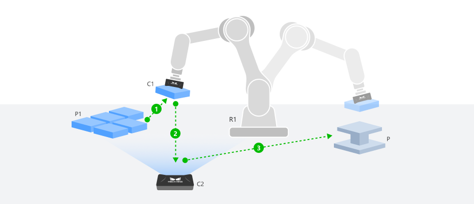
After the robot picks a target object, it moves to a fixed image-capturing point where a 3D camera captures the point cloud of the target object and calculates the actual pose. Meanwhile, the real-time pose of the placement target is obtained through the placement target recognition project. Combined with the ideal assembly relationship established during the teaching phase, the corrected assembly TCP pose is dynamically calculated and output.
|
The following uses a 3D camera C1 with EIH mounting and another 3D camera C2 with ETH mounting as an example: Camera C1 is used for the initial positioning, picking, and placement target recognition, and Camera C2 is used for the second image capture of the picked target object at a fixed image-capturing point. The assembly TCP pose correction process is described below. Other camera types or mounting methods can refer to this process and adapt based on actual conditions. |
Configure Step Ports
-
Click the Config wizard button to open the pose transformation tool and select Pose correction for assembly.
-
In the parameter area on the right, select the assembly scenario by setting the camera type to 3D camera and the placement type to Non-fixed placement target.
-
Click the OK button to complete the configuration.
The input and output ports after configuration are as follows:
Input
| Input port | Data type | Description |
|---|---|---|
TCP at Capture |
Pose [] |
The TCP recorded during teaching when the robot, after picking up the target object, moves to the secondary image-capturing point to acquire an image of the target object. This TCP value is read from the teach pendant in the robot frame. |
Target Object Pose at Capture |
Pose [] |
The real-time pose of the picked target object in the robot frame during the second image capture. |
Real-Time Placement Target Pose |
Pose [] |
The real-time pose of the placement target in the robot frame. |
Output
| Output port | Data type | Description |
|---|---|---|
Assembly Pose |
Pose [] |
The corrected assembly pose obtained by applying a rotational transformation to the input taught TCP pose and combining it with other input poses. This output pose can be directly fed into the "Output" Step. |
Record Taught Poses (Teaching Phase)
Before running the Step, a complete teaching process using a standard target object and a reference placement position is required to collect the following data.
-
Create the placement target point cloud model.
-
Use the teach pendant to control the robot to pick a standard target object and move it to the ideal assembly pose, ensuring that the target object P1 is fully aligned with the placement position P. The gripper must remain closed and the target object must remain picked throughout the process. The gripper must remain closed and the target object must remain picked throughout the process. After the robot comes to a stop, record the robot TCP pose at this point. This pose will be used for creating the placement target point cloud model.
-
While the target object remains picked, move the robot to smoothly move the target object out of the placement area, ensuring the placement position is restored to an empty state without any change in its pose.
-
Move the robot to an appropriate image-capturing position and record this point as the fixed image-capturing point for the placement target.
-
At this image-capturing point, trigger Camera C1 to capture the placement target point cloud. Create a placement target point cloud model by jogging the robot using this point cloud for subsequent model matching.
When creating the point cloud model by jogging the robot, the robot TCP pose recorded at the ideal assembly state in the previous step should be used as the taught placing pose, and the robot flange pose and TCP (the pose of the tool relative to the robot flange) at this moment should be entered in the "Teach pick point" step of the model creation process.
-
-
Record the TCP at capture and create the target object point cloud model.
-
While the target object remains picked, use the teach pendant to move the target object to an appropriate secondary image-capturing point, ensuring Camera C2 can capture the target object features completely and clearly. Set this as the fixed image-capturing point and record the TCP pose at this point as the "TCP at Capture". This pose will be used for creating the target object point cloud model and will serve as the reference baseline for pose correction.
-
At the current image-capturing point, trigger Camera C2 to capture the target object point cloud. Create a target object point cloud model by jogging the robot using this point cloud for subsequent model matching.
When creating the point cloud model by jogging the robot, the TCP at Capture recorded in the previous step should be used as the taught pick pose, and the robot flange pose and TCP (the pose of the tool relative to the robot flange) at this moment should be entered in the "Teach pick point" step of the model creation process.
-
-
Configure Step input.
Connect the acquired TCP at Capture to the corresponding input port of the "Advanced Pose Transformation" Step to prepare for the subsequent Running phase.
Obtain Real-Time Pose (Running Phase)
During the running phase, the real-time poses of both the target object and the placement target need to be obtained for assembly TCP pose correction.
-
Obtain the target object pose at capture.
-
After the robot picks the actual target object, it moves to the secondary image-capturing point determined during teaching, and triggers Camera C2 to capture the target object point cloud.
-
Preprocess the captured point cloud, and use the target object point cloud model created during the teaching phase in the "3D Matching" Step for matching, outputting the pose of the target object in the camera reference frame.
-
Transform this pose to the robot frame and pass it to the corresponding input port of the "Advanced Pose Transformation" Step through Steps such as "Global Variable" or "Save Result to File".
-
-
Obtain the real-time placement target pose.
-
When the robot moves to the placement target image-capturing point determined during teaching, trigger Camera C1 to capture the placement target point cloud. Use the placement target point cloud model created during the teaching phase in the "3D Matching" Step for matching to obtain the real-time pose of the placement target in the camera reference frame.
-
Transform this pose to the robot frame and connect it to the "Real-Time Placement Target Pose" input port of the "Advanced Pose Transformation" Step.
-
|
To avoid mutual interference between the target object and the placement target during visual recognition, it is recommended to obtain the target object pose at capture and the real-time placement target pose in two separate Mech-Vision projects, and pass the results through Steps such as "Global Variable" or "Save Result to File". |
Correct Assembly Pose at a Fixed Placement Target Using a 2D Camera
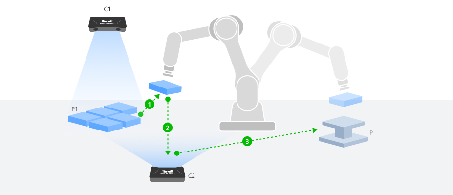
After the robot picks a target object, it moves to a fixed image-capturing point where a 2D camera captures the target object image. The 2D recognition result is converted to a 3D pose, and combined with the taught fixed placement target pose, the corrected assembly flange pose is calculated.
|
The following uses a 3D camera C1 with ETH mounting and a 2D camera C2 with ETH mounting as an example: Camera C1 is used for the initial positioning and picking of the target object, and Camera C2 performs the second image capture of the picked target object at a fixed image-capturing point. The assembly TCP pose correction process is described below. Other camera types or mounting methods can refer to this process and adapt based on actual conditions. |
Configure Step Ports
-
Click the Config wizard button to open the pose transformation tool and select Pose correction for assembly.
-
In the parameter area on the right, select the assembly scenario by setting the camera type to 2D camera and the placement type to Fixed placement target.
-
Click the OK button to complete the configuration.
The input and output ports after configuration are as follows:
Input
| Input port | Data type | Description |
|---|---|---|
Flange Pose at Capture |
Pose [] |
The flange pose recorded during teaching when the robot, after picking up the target object, moves to the secondary image-capturing point to acquire an image of the target object. This flange pose is read from the teach pendant in the robot frame. |
Target Object Pose at Capture |
Pose [] |
The real-time pose of the picked target object in the robot frame during the second image capture. |
Fixed Placement Target Pose |
Pose [] |
The flange pose recorded during teaching when the robot is jogged to move the target object to its designated placing point for assembly. This flange pose is read from the teach pendant in the robot frame. |
Output
| Output port | Data type | Description |
|---|---|---|
Assembly Pose |
Pose [] |
The corrected assembly pose obtained by applying a rotational transformation to the input taught flange pose and combining it with other input poses. This output pose can be directly fed into the "Output" Step. |
Record Taught Poses (Teaching Phase)
Before running the Step, a complete teaching process using a standard target object and a reference placement position is required to collect the following data.
-
Record the fixed placement target pose.
-
Manually place the standard target object at the target assembly position, ensuring that the target object P1 is fully aligned with the placement position P, with the posture in the ideal assembly state.
-
Use the teach pendant to control the robot end tool to pick the target object and adjust it to the ideal assembly pose. After the robot comes to a stop, record the robot flange pose at this point as the "Fixed Placement Target Pose".
-
-
Create the target object 2D template.
-
While the target object remains picked, use the teach pendant to move the target object to an appropriate secondary image-capturing point, ensuring Camera C2 can capture the target object features completely and clearly. Set this as the fixed image-capturing point and record the flange pose at this point as the "Flange Pose at Capture".
-
.. At the current image-capturing point, trigger Camera C2 to capture the target object image. Create a target object 2D template based on this image for subsequent model matching.
-
-
Configure Step input.
Connect the acquired Fixed Placement Target Pose and Flange Pose at Capture to the corresponding input ports of the "Advanced Pose Transformation" Step to prepare for the subsequent running phase.
Obtain Real-Time Pose (Running Phase)
During the running phase, the real-time pose of the target object at the time of the second image capture needs to be obtained for assembly flange pose correction.
-
After the robot picks the actual target object, it moves to the secondary image-capturing point determined during teaching, and triggers Camera C2 to capture the target object image.
-
After preprocessing the captured image, use the target object 2D template created during the teaching phase in the "2D Matching" Step for matching, and output the 2D pose of the target object in the camera reference frame.
-
Use the "Convert 2D Point to 3D Pose" Step to convert this 2D pose to a 3D pose in the robot frame, and connect it to the "Target Object Pose at Capture" input port of the "Advanced Pose Transformation" Step.
Correct Assembly Pose at a Non-Fixed Placement Target Using a 2D Camera
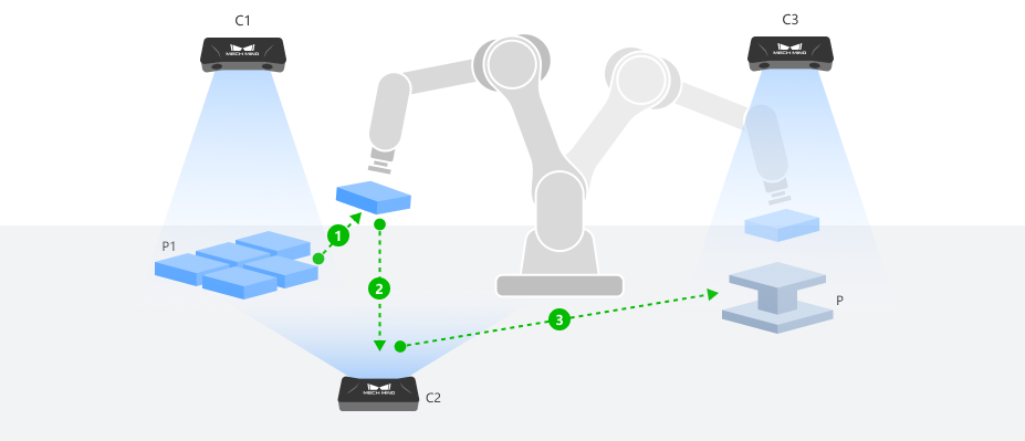
After the robot picks a target object, it moves to a fixed image-capturing point where a 2D camera captures the target object image. The 2D recognition result is converted to a 3D pose. Meanwhile, the real-time pose of the placement target is obtained through the placement target recognition project. Combined with the ideal assembly relationship established during the teaching phase, the corrected assembly flange pose is dynamically calculated and output.
|
The following uses three 2D cameras with ETH mounting as an example: Cameras C1 and C3 are used for the initial positioning, picking, and placement target recognition respectively, and Camera C2 is used for the second image capture of the picked target object at a fixed image-capturing point. The assembly TCP pose correction process is described below. Other camera types or mounting methods can refer to this process and adapt based on actual conditions. |
Configure Step Ports
-
Click the Config wizard button to open the pose transformation tool and select Pose correction for assembly.
-
In the parameter area on the right, select the assembly scenario by setting the camera type to 2D camera and the placement type to Non-fixed placement target.
-
Click the OK button to complete the configuration.
The input and output ports after configuration are as follows:
Input
| Input port | Data type | Description |
|---|---|---|
Flange Pose at Capture |
Pose [] |
The flange pose recorded during teaching when the robot, after picking up the target object, moves to the secondary image-capturing point to acquire an image of the target object. This flange pose is read from the teach pendant in the robot frame. |
Target Object Pose at Capture |
Pose [] |
The real-time pose of the picked target object in the robot frame during the second image capture. |
Taught Placing Pose |
Pose [] |
The flange pose recorded during teaching when the robot is jogged to move the target object to its designated placing point for assembly. |
Taught Placement Target Pose |
Pose [] |
The pose of the placement target in the robot frame during teaching the placing pose. |
Real-Time Placement Target Pose |
Pose [] |
The real-time pose of the placement target in the robot frame. |
Output
| Output port | Data type | Description |
|---|---|---|
Assembly Pose |
Pose [] |
The corrected assembly pose obtained by applying a rotational transformation to the input taught flange pose and combining it with other input poses. This output pose can be directly fed into the "Output" Step. |
Record Taught Poses (Teaching Phase)
Before running the Step, a complete teaching process using a standard target object and a reference placement position is required to collect the following data.
-
Record the taught placing pose.
-
Manually place the standard target object at the target assembly position, ensuring that the target object P1 is fully aligned with the placement position P, with the posture in the ideal assembly state.
-
Use the teach pendant to control the robot end tool to pick the target object and adjust it to the ideal assembly pose. After the robot comes to a stop, record the robot flange pose at this point as the "Taught Placing Pose".
-
-
Create the placement target template and record the taught placement target pose.
-
While the target object remains picked, move the robot to smoothly move the target object out of the placement area, ensuring the placement position is restored to an empty state without any change in its pose.
-
Move the robot to a position that does not obstruct the placement target’s field of view, ensuring Camera C3 can capture the empty placement target completely, and record this point as the fixed image-capturing point for the placement target.
-
At this image-capturing point, trigger Camera C3 to capture the placement target image. Create a placement target 2D template based on this image for subsequent model matching.
-
In the "2D Matching" Step, use this template to match the placement target image. Then use the "Convert 2D Point to 3D Pose" Step to output the 3D pose of the placement target in the robot frame at this moment as the "Taught Placement Target Pose".
-
-
Create the target object 2D template.
-
While the target object remains picked, use the teach pendant to move the target object to an appropriate secondary image-capturing point, ensuring Camera C2 can capture the target object features completely and clearly. Set this as the fixed image-capturing point and record the flange pose at this point as the "Flange Pose at Capture".
-
.. At the current image-capturing point, trigger Camera C2 to capture the target object image. Create a target object 2D template based on this image for subsequent model matching.
-
-
Configure Step input.
Connect the acquired Taught Placing Pose, Taught Placement Target Pose, and Flange Pose at Capture to the corresponding input ports of the "Advanced Pose Transformation" Step to prepare for the subsequent running phase.
Obtain Real-Time Pose (Running Phase)
During the running phase, the real-time poses of both the target object and the placement target need to be obtained for assembly flange pose correction.
-
Obtain the target object pose at capture.
-
After the robot picks the actual target object, it moves to the secondary image-capturing point determined during teaching, and triggers Camera C2 to capture the target object image.
-
After preprocessing the captured image, use the target object 2D template created during the teaching phase in the "2D Matching" Step for matching, and output the 2D pose of the target object in the camera reference frame.
-
Use the "Convert 2D Point to 3D Pose" Step to convert this 2D pose to a 3D pose in the robot frame, and connect it to the "Target Object Pose at Capture" input port of the "Advanced Pose Transformation" Step.
-
-
Obtain the real-time placement target pose.
-
When the robot moves to the placement target image-capturing point determined during teaching, trigger Camera C3 to capture the placement target image. Use the placement target 2D template created during the teaching phase in the "2D Matching" Step for matching, and output the 2D pose of the placement target in the camera reference frame.
-
Use the "Convert 2D Point to 3D Pose" Step to convert this 2D pose to a 3D pose in the robot frame. Pass it to the "Advanced Pose Transformation" Step through "Global Variable" or "Save Result to File" Steps.
-
|
To avoid mutual interference between the target object and the placement target during visual recognition, it is recommended to obtain the target object pose at capture and the real-time placement target pose in two separate Mech-Vision projects, and pass the results through Steps such as "Global Variable" or "Save Result to File". |