Hand-Eye Calibration Results Check and Analysis
For the calibrated extrinsic parameters, you need to check whether the calibration accuracy meets the requirements. If the error falls outside the normal range, you should diagnose and solve the problems that are responsible for the error before recalibrating to obtain qualified extrinsic parameters.
Validate Calibration Results
This section outlines four quick methods to validate calibration results.
| Validation Method | Application Scenarios | Note |
|---|---|---|
Scenarios with low accuracy requirements |
For a rough validation of calibration results |
|
Roughly Check Coincidence Degree between the Point Cloud of the Robot and the Robot Model |
Scenarios with low accuracy requirements |
For a rough validation of calibration results |
Check the Shift of the Calibration Board’s Point Cloud in Reference to a Fixed Point |
Scenarios with low accuracy requirements |
For a rough validation of calibration results |
Use the Extrinsic Parameter Accuracy Validation Tool to Validate Extrinsic Parameters |
Scenarios with high accuracy requirements |
For a comprehensive and quantitative validation of calibration results |
View Error Point Cloud in Point Cloud Viewer
After calculating the camera extrinsic parameters, perform the following operations:
-
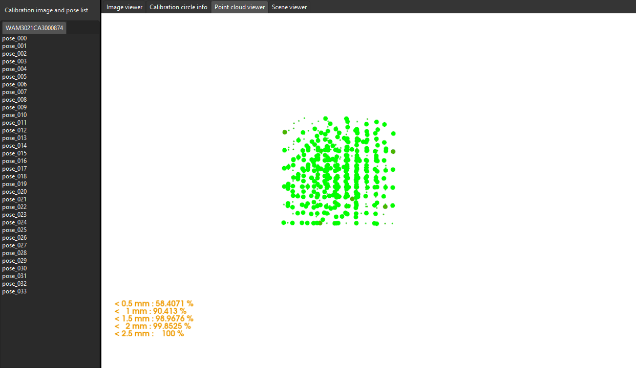
In the Calculate extrinsic parameters step, view the error point cloud in the right Point cloud viewer panel after the calibration calculation is complete.
The error point cloud shows the deviation between the calculated value and the actual value of the circles on the calibration board at each calibration point. For the detailed description, please refer to Error Point Cloud Description. -
Confirm that the calibration accuracy error meets the project’s requirements. Find the error value with the 100% percentage to get the rough calibration accuracy.
The point cloud view after calibration using multiple random calibration board poses is shown in the figure below. The calibration error is within ±2.5 mm.
|
In general, the standards for acceptable calibration error in the point cloud are as follows:
The above standards are just for reference. Please follow the specific accuracy requirement of the real application. |
The color of the point represents the error level. The darker the color is, the greater the error of the point.
To view the points at each error level, press the number keys 0–9 in the Point cloud viewer panel. Points with an error at the specified level will be highlighted.
Taking an error level of 0.5 mm as an example, key 0 corresponds to points with an error less than 0.5 mm, key 1 corresponds to points with an error between 0.5 mm and 1 mm, and so on.
The following figure displays all points with an error less than ±0.5 mm (by pressing the number key 0).

The following figure displays all points with error between 2.0 mm and 2.5 mm (by pressing the number key 4).

Roughly Check Coincidence Degree between the Point Cloud of the Robot and the Robot Model in Scene Viewer
| This validation method applies to the calibration scenarios in both ETH and EIH setups. For calibration in the ETH setup, the camera needs to capture the point cloud of the robot arm. For calibration in the EIH setup, the camera needs to capture the point cloud of the robot base. In the EIH scenario, the robot’s degrees of freedom and workspace must allow its end to approach the base, enabling the camera to capture images of the base. |
Hand-eye calibration in the ETH setup:
After calculating the camera extrinsic parameters, perform the following operations:
-
After calibration, move the robot arms into the field of view of the camera.
-
In the Calculate extrinsic parameters step, click the Acquire by camera button in the 2 Auxiliary tool area. This operation triggers the camera to capture images.
-
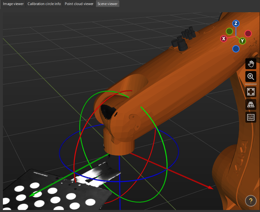
In the right Scene viewer panel, visually check coincidence degree between the point cloud of the real robot and the robot model. If the point cloud of the robot roughly coincides with the robot model, the calibration is successful.
As shown in the figure, the color part is the robot model, the black part is the robot point cloud. From the figure, you can learn that the robot model and the robot point cloud roughly coincides. This indicates that the calibration result can be used.
Hand-eye calibration in the EIH setup:
After calculating the camera extrinsic parameters, please perform the following operation:
-
Move the robot end effector to a position where the camera can capture images of the base.
-
In the Calculate extrinsic parameters step, click the Acquire by camera button in the 2 Auxiliary tool area. This operation triggers the camera to capture images.
-
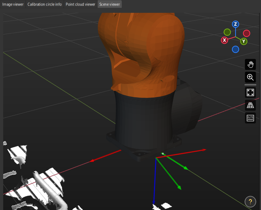
In the right Scene viewer panel, visually check coincidence degree between the point cloud of the real robot and the robot model. If the point cloud of the robot roughly coincides with the robot model, the calibration is successful.
As shown in the figure, the color part is the robot model, the black part is the robot point cloud. From the figure, you can learn that the robot model and the robot point cloud roughly coincides. This indicates that the calibration result can be used.
|
Check the Shift of the Calibration Board’s Point Cloud in Reference to a Fixed Point in Scene Viewer
| If the camera cannot capture an image of the base due to robot degrees of freedom or workspace limitations in the EIH setup, you can use this method to roughly validate the calibration results. |
After calculating the camera extrinsic parameters, perform the following operations:
-
Place the calibration board on a fixed position.
-
Open Mech-Viz, add a fixed point, and make sure that this point coincides with the crosshair of a calibration circle on the calibration board.
-
Find the “Fixed-Point Move” Step from the Step library and then drag it to the graphical programming workspace.
-
Select this Step, set the Waypoint type parameter to “Target object pose” on the parameter panel, adjust the X, Y and Z values of the pose to make this point coincide with the crosshair of a calibration circle on the calibration board.
-
-
Control the robot to change the pose of the camera for several times, and click the Recalculate extrinsic parameters button in the Calculate camera parameters step of the calibration process. This operation will trigger the camera to capture images.
-
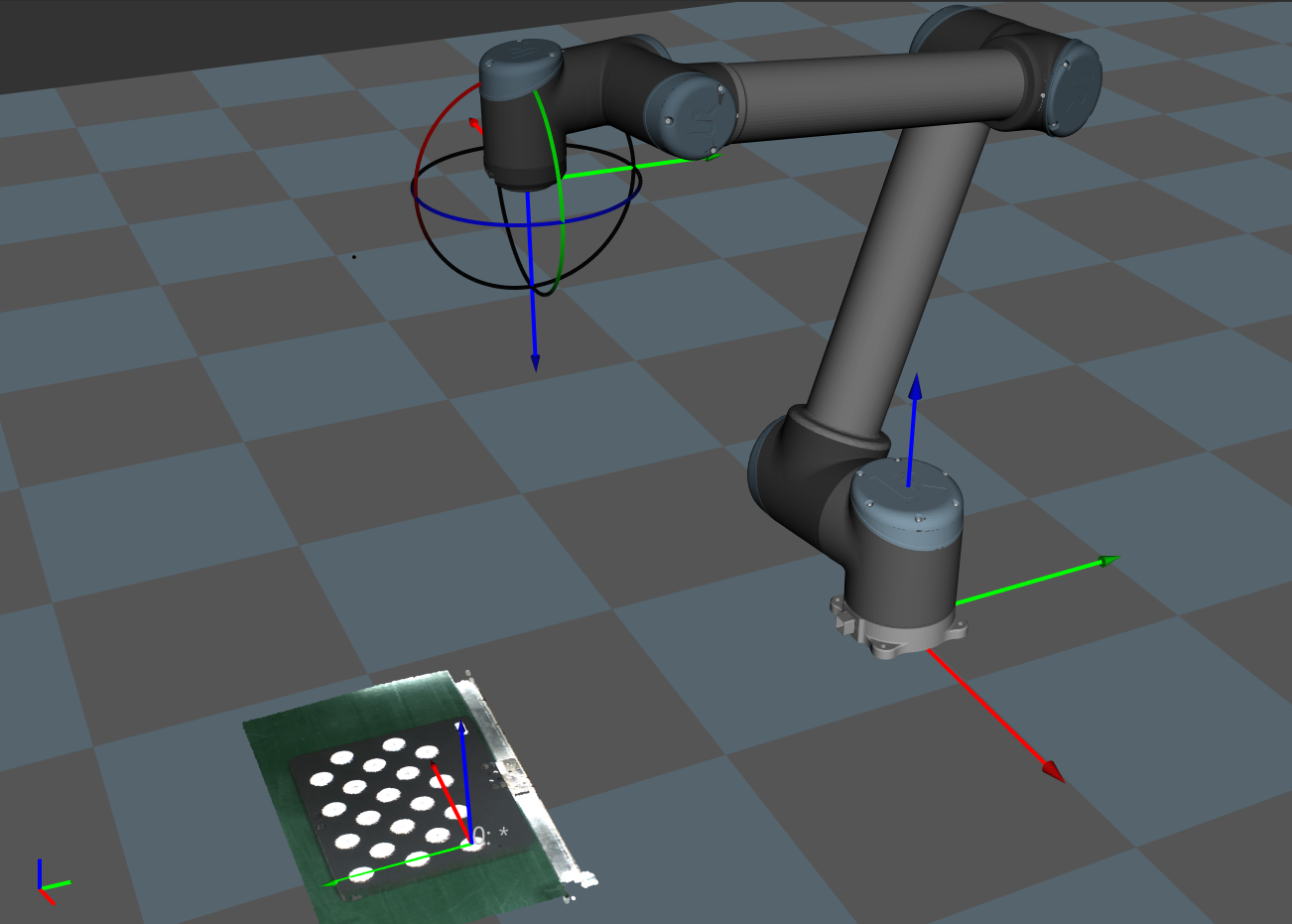
Check whether the calibration board’s point cloud has a significant shift in reference to the fixed point in Scene viewer.
If the calibration board’s point cloud does not have a significant shift, the calibration is successful.
|
Use the Extrinsic Parameter Accuracy Validation Tool to Validate Extrinsic Parameters
Mech-Vision has provided the extrinsic parameter accuracy validation tool to analyze extrinsic parameter errors in the eye-to-hand setup and eye-in-hand setup. The error analysis covers the check of the extrinsic parameter errors and the robot absolute accuracy errors.
In the Calculate extrinsic parameters step, click Extrinsic parameter accuracy to open the tool. Please refer to the tool’s guidance to validate the extrinsic parameter accuracy and generate the final evaluation report.
Alternatively, you can open the tool by selecting in the menu bar.
For details, please refer to Analyze extrinsic parameter errors.
Analyze Calibration Results
Check Extrinsic Parameter Calibration Report
For the automatic calibration and the manual calibration using the multiple random calibration board poses method for six-axis robots, Mech-Vision’s camera calibration tool has provided the “extrinsic parameter calibration report” function.
In the Calculate extrinsic parameters step of the calibration process, after you have got the extrinsic parameters by clicking the Calculate extrinsic parameters button, you can click the View extrinsic parameter calibration report button.
The Mech-Vision’s camera calibration tool will check the extrinsic parameter calibration results based on the collected calibration data, and generate the extrinsic parameter calibration report.
This report displays the results of the following checks and improvement recommendations:
-
Euler angle convention check
-
Robot absolute accuracy check
If the camera accuracy in the report does not meet the requirements, please follow the recommendation to troubleshoot the camera accuracy errors.
Improve the Accuracy of Extrinsic Parameters
If the accuracy of the calibrated extrinsic parameter data is below standard, you need to follow the following instructions to inspect the data and find the root cause for the errors.
Inspect Calibration Data
Please check the calibration data in the following order to locate the root cause.
Calibration data refers to the calibration point data generated during the calibration process and is stored in calib_data.json. This file records data such as the flange poses at calibration points and calibration circle data.
To inspect calibration data, follow these steps:
-
Open Mech-Vision, and click the Camera Calibration button in the toolbar. The Configuration before Calibration window will be prompted.
-
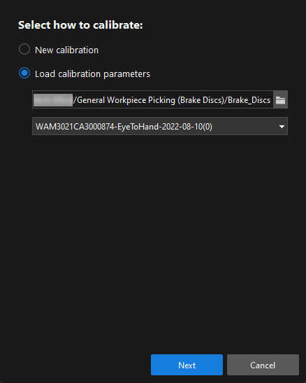
In the Select how to calibrate window, select the Load calibration parameters radio button, choose the calibration parameter file, and then click the Next button.
When selecting the calibration parameter file path, choose the path to the folder containing the calibration parameter file.
-
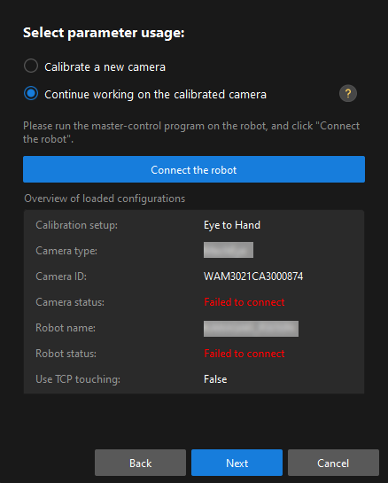
In the Select parameter usage window, select the Continue working on the calibrated camera radio button, and then click the Next button.
-
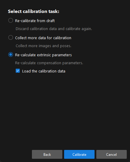
In the Select calibration task window, select the Re-calculate extrinsic parameters radio button, select the Load the calibration data checkbox, and then click the Calibrate button.
-
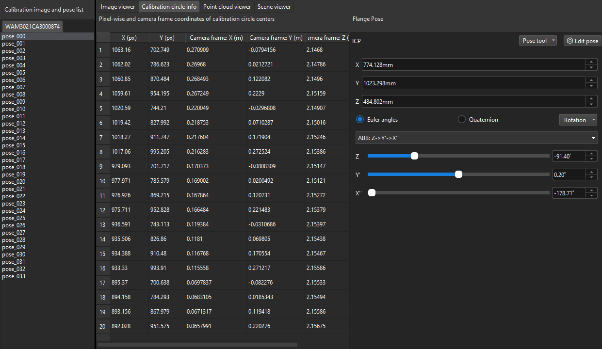
In the Calibrate extrinsic parameters step of the calibration process, click a calibration point in the Calibration image and pose list panel (such as pose_000), and click the Calibration circle info tab to view the robot flange pose and the calibration circle data at this calibration point.
|
In the figure, X (pixel) and Y (pixel) columns represent the pixel coordinates of the calibration circle centers in the current 2D image. Camera frame: X(m)/Y(m)/Z(m) columns represent the coordinates of the calibration circle centers in the camera reference frame in the current depth map. |
Please inspect the calibration data from the following aspects:
-
Check if the flange poses change between different sets of calibration points in the pyramid calibration path.
Only calibration points in the pyramid calibration path are checked, excluding the rotating sets of calibration points. This inspection is applied to calibration scenarios using the multiple random calibration board poses method to collect calibration data. In the Calibration image and pose list panel, select the calibration points one by one (such as pose_000), and then click the Calibration circle info tab to view the robot flange pose at the calibration point. When the robot moves along the pyramid calibration path, it will move along its base coordinate or flange without rotating. Therefore, the Euler angles will keep consistent throughout the entire procedure.
Depending on the precision level of the robot, the Euler angles might fluctuate differently. If the fluctuation exceeds 1 degree, the robot might have lost its zero position or have bad precision.
Solution: in this case, hand-eye calibration should not be continued. You should check the robot’s zero position and fix the precision issue before continuing to calibrate.
-
Check if the “Error of measured average calibration circle interval” of the calibration points exceeds the standard value.
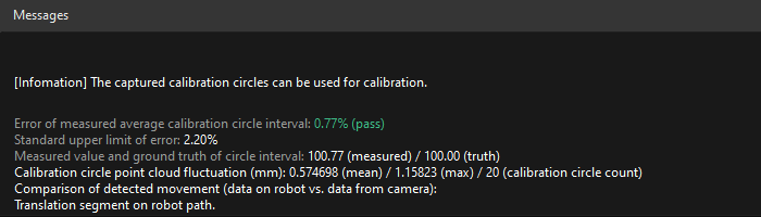
In the Calibration image and pose list panel, select the calibration point, and view Error of measured average calibration circle interval in the Messages panel.
If it exceeds the standard value, the calibration point will turn to yellow for a warning. As part of the intrinsic parameters check result, Error of measured average calibration circle interval can partly reflect the current error in the camera intrinsic parameters.

Solution: for projects with low precision requirements, intrinsic parameters with errors that slightly exceed the standard may still be used. For situations where high precision is required or the errors greatly exceed the standard, it is recommended to re-calibrate the intrinsic parameters or replace the camera.
-
Check if the max value of the “Calibration circle point cloud fluctuation” exceeds 3 mm
In the Calibration image and pose list panel, select the calibration point, and view Calibration circle point cloud fluctuation in the Messages panel. Calibration circle point cloud fluctuation represents the overall fluctuation of the plane containing the coordinates of all the calibration circle centers. This value directly influences the accuracy of the extrinsic parameters. The higher a project’s precision requirements are, the lower the fluctuation value should be.
Generally, the max acceptable value for the fluctuation is 3 mm. If more than three calibration points have point cloud fluctuation greater than 3 mm, the whole accuracy is not acceptable. You should troubleshoot the issue and perform re-calibration.
Potential factors that might cause point cloud fluctuation are as follows:
Possible cause 1: The Surface Smoothing and Outlier Removal features in Mech-Eye Viewer have not been enabled, or the Gain is applied.
Solution: Change Surface Smoothing and Outlier Removal to “Normal” and set Gain to zero. If the issue persists after completing the above steps, shading must be applied to the site.
Possible cause 2: When automatic calibration is performed in the ETH setup, the calibration board is not securely mounted on the robot flange. When the robot is too fast, the calibration board might vibrate during the calibration process, thus causing excessive point cloud fluctuation.
Solution: Lower the speed limit on the robot, install the calibration board firmly, and extend the wait time before capturing a new image at each waypoint.