Calibration Results Check and Analysis
For the calibrated extrinsic parameters, you need to check whether the calibration accuracy meets the requirements. If the error fall outside the normal range, you should diagnose and solve the problems that are responsible for the error before recalibrating to obtain qualified extrinsic parameters.
Verify Calibration Results
Check Error Point Cloud in Point Cloud Viewer
In the Calculate camera parameters step, the Point cloud viewer panel will display the point cloud showing the calibration error, as shown in the following figure. The error point cloud shows the deviation between the calculated value and the actual value of the circles on the calibration board.
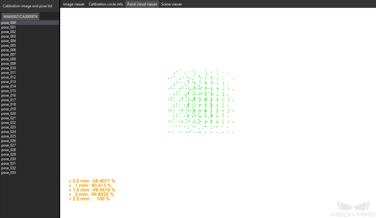
The color of the point represents the error level (one error level per 0.5 mm of deviation). The darker the color is, the greater the error of the point.
To view the points at each error level, in the Point cloud viewer panel, press the number keys 0–9. The software will highlight the points in the corresponding error level (0 corresponds to points with error less than 0.5 mm, 1 corresponds to points with errors between 0.5 mm and 1mm, so on and so forth).
The following figure displays all points with error less than 0.5 mm (by pressing the number key 0).
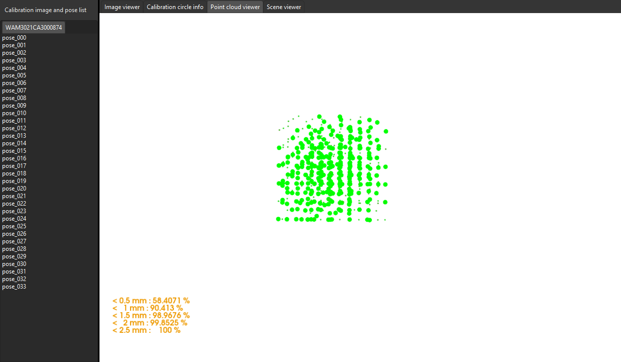
The following figure displays all points with error between 2.0 mm and 2.5 mm (by pressing the number key 4).

Roughly Check Coincidence Degree between the Point Cloud of the Robot and the Robot Model in Scene Viewer (Suitable for the Eye-to-Hand Setup)
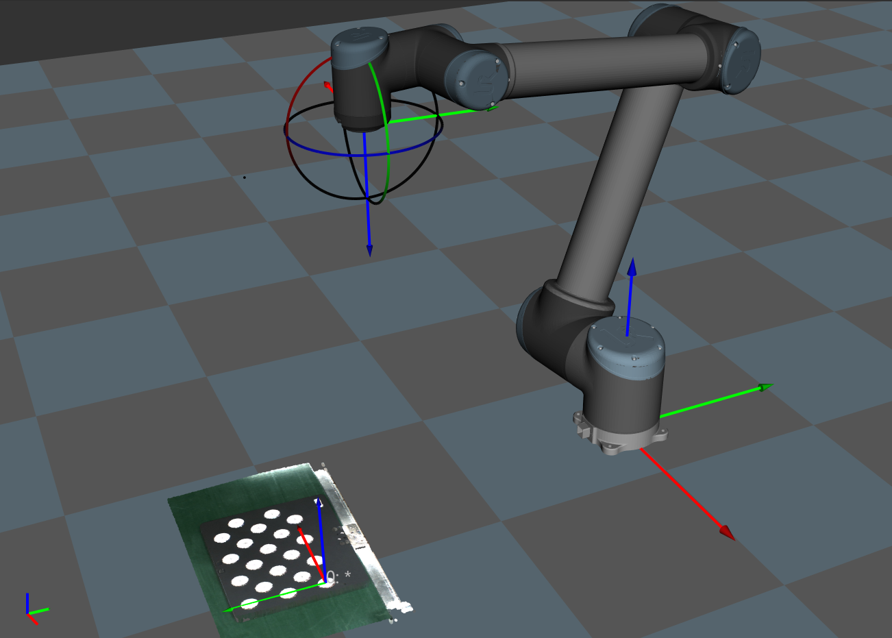
You can check calibration results roughly by inspecting the coincidence degree between the point cloud of the robot and the robot model in Scene Viewer. To do so, follow these steps:
-
After calibration, move the robot arms into the FOV of the camera.
-
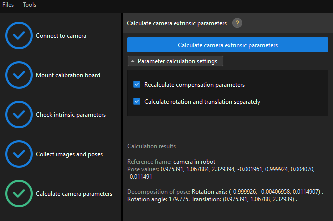
In the Calculate camera parameters step, click the Calculate camera extrinsic parameters button. This operation will trigger the camera to capture images.
-
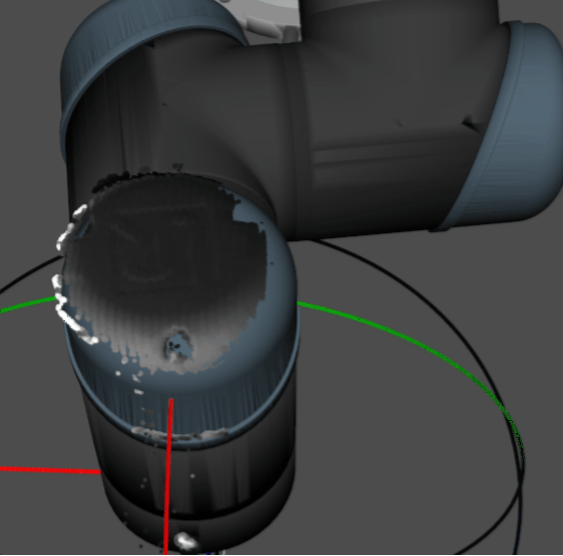
Click Scene viewer to check the coincidence degree between the point cloud of the robot and the robot model.
If the point cloud of the robot roughly coincides with the robot model, the calibration is successful.
-
Be aware that the robot simulation cannot match the real robot completely, and thus cannot be used to fine-tune the extrinsic parameters.
-
Besides Scene viewer, you can also check the coincidence degree between the point cloud of the robot and the robot model in Mech-Viz.
-
Check the Shift of the Calibration Board’s Point Cloud in Reference to a Fixed Point in Scene Viewer (Suitable for the Eye-in-Hand Setup)
You can check calibration results roughly by inspecting the shift of the calibration board’s point cloud (to be specific, the crosshair of a calibration circle on the board) in reference to a fixed point in Scene Viewer. To do so, follow these steps:
-
Place the calibration board on a fixed position.
-
Open Mech-Viz, add a fixed point, and make sure that this point coincides with the crosshair of a calibration circle on the calibration board.
-
Find the “Fixed-Point Move” Step from the Step library and then drag it to the graphical programming workspace.
-
Select this Step, set the Waypoint type parameter to “Workobject pose” on the parameter panel, adjust the X, Y and Z values of the pose to make this point coincide with the crosshair of a calibration circle on the calibration board.
-
-
Control the robot to change the pose of the camera for several times, and click the Recalculate camera extrinsic parameters button in the Calculate camera parameters step of the calibration process. This operation will trigger the camera to capture images.
-
Check whether the calibration board’s point cloud has a significant shift in reference to the fixed point in Scene viewer.
If the calibration board’s point cloud does not have a significant shift, the calibration is successful.
|
Analyze Calibration Results
Calibration Result Evaluation Standard
For the calibrated extrinsic parameters, you need to check whether the calibration accuracy meets the requirements. In general, the standards for acceptable calibration error in the point cloud are as follows:
-
For common projects, all data points should have errors lower than 3 mm (< 3 mm: 100%).
-
For high-precision projects, all data points should have errors lower than 2 mm (< 2 mm: 100%).
-
For palletizing and depalletizing projects, all data points should have errors lower than 5 mm (< 5 mm: 100%).
The above standards are just for reference. Please follow the specific accuracy requirement of the real application.
Factors Affecting the Calibration Accuracy
If the calibration accuracy is below standard, you need to follow the following instructions to inspect the calibration data and find the root cause for the errors.
Inspect Calibration Data
Calibration data refers to the calibration point data generated during the calibration process and is stored in calib_data.json. This file records data such as the flange poses at calibration points and calibration circle data.
To inspect calibration data, follow these steps:
-
Open Mech-Vision, and click the Camera Calibration (Standard) button in the toolbar. The Configuration before Calibration window will be prompted.
-
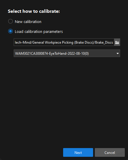
In the Select how to calibrate window, select the Load calibration parameters radio button, choose the calibration parameter file, and then click the Next button.
-
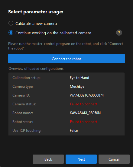
In the Select parameter usage window, select the Continue working on the calibrated camera radio button, and then click the Next button.
-
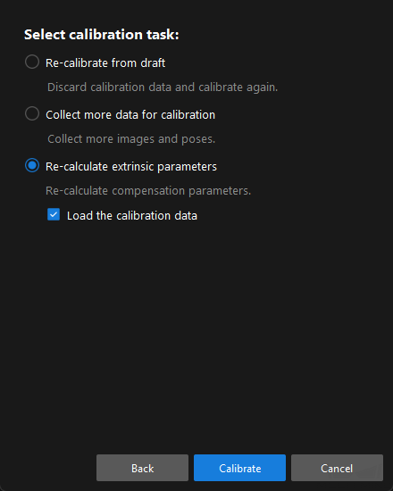
In the Select calibration task window, select the Re-calculate extrinsic parameters radio button, select the Load the calibration data checkbox, and then click the Calibrate button.
-
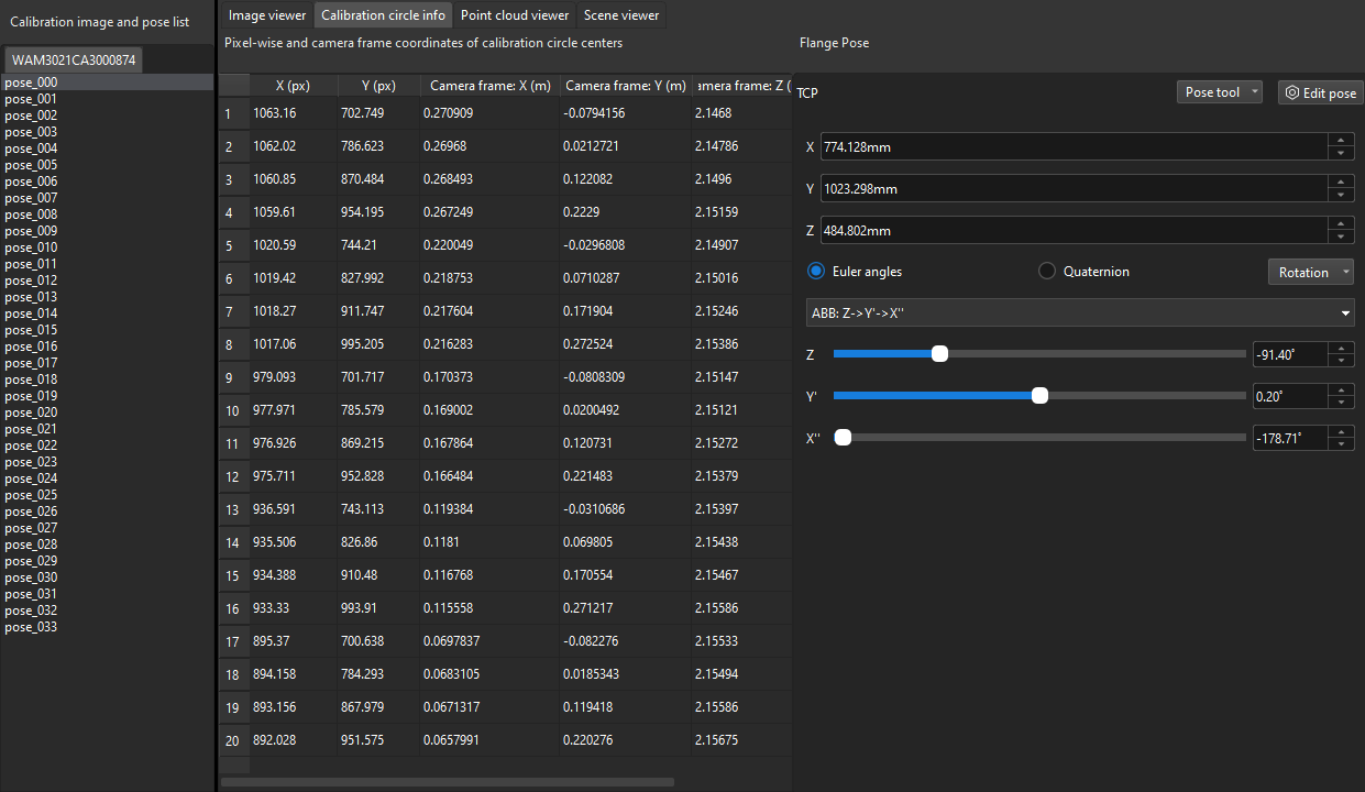
In the Calibrate camera parameter step, click a calibration point in the Calibration image and pose list panel (such as pose_000), and click the Calibration circle info tab to view the robot flange pose and the calibration circle data at this calibration point.
|
In the figure, X (pixel) and Y (pixel) columns represent the pixel coordinates of the center points of the calibration circles in the current 2D image; Camera frame: X(m)/Y(m)/Z(m) columns represent the coordinates of the center points relative to the camera reference frame in the current depth image. |
Please inspect the calibration data from the following aspects:
-
Check if the flange poses change between different sets of calibration points in the pyramid calibration path.
Only calibration points in the pyramid calibration path are checked, excluding the rotating sets of calibration points. This inspection is applied to calibration scenarios using the multiple random calibration board poses method to collect calibration data. In the Calibration image and pose list panel, select the calibration points one by one (such as pose_000), and then click the Calibration circle info tab to view the robot flange pose at the calibration point. When the robot will move along the pyramid calibration path, it moves along its base coordinate or flange without rotating. Therefore, the Euler angles will keep consistent throughout the entire procedure.
Depending on the precision level of the robot, the Euler angles might fluctuate differently. If the fluctuation exceeds 1 degree, the robot might have lost its zero position or have bad precision.
Solution: in this case, hand-eye calibration should not be continued. You should check the robot’s zero position and fix the precision issue before continuing to calibrate.
-
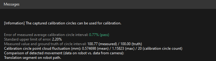
Check if the "Error of measured average calibration circle interval" of the calibration points exceeds the standard value
In the Calibration image and pose list panel, select the calibration point, and view Error of measured average calibration circle interval in the Messages panel.
If it exceeds the standard value, the calibration point will turn to yellow for warning. As part of the intrinsic parameters check result, Error of measured average calibration circle interval can partly reflect the current error in the camera intrinsic parameters.

Solution: for projects with low precision requirements, intrinsic parameters with errors that slightly exceed the standard may still be used. For situations where high precision is required or the errors greatly exceed the standard, it is recommended to re-calibrate the intrinsic parameters or replace the camera.
Errors in intrinsic parameters will affect the calibration result, but if it is within the normal range, it is generally acceptable.
-
Check if the max value of the "Calibration circle point cloud fluctuation" exceeds 3 mm
In the Calibration image and pose list panel, select the calibration point, and view Calibration circle point cloud fluctuation in the Messages panel. Calibration circle point cloud fluctuation represents the overall fluctuation of the plane containing the coordinates of all the circles' center points. This value directly influences the accuracy of the extrinsic parameters.
The higher a project’s precision requirements are, the lower the fluctuation value should be. Generally, the max acceptable value for the fluctuation is 3 mm. If more than three calibration points have point cloud fluctuation greater than 3 mm, you should troubleshoot the issue and perform re-calibration.
Potential factors that might cause point cloud fluctuation are as follows:
Reason 1: The 3D camera exposure parameters are not optimized. It is likely that the Surface Smoothing and Outliers Removal options are disabled or that Gain is enabled. Solution: Change Cloud Smoothing and Outliers Removal to "Normal", set Gain to zero, and adjust the 3D exposure parameters accordingly. If the point cloud of the calibration circles is still fragmented, on-site shading is required. Reason 2: When automatic calibration is performed in the ETH setup, the calibration board is not securely mounted on the robot flange. When the speed of the robot is too fast, the calibration board might vibrate during the calibration process, thus causing excessive point cloud fluctuation. Solution: Lower the speed limit on the robot, install the calibration board firmly, and extend the wait time before capturing a new image at each waypoint.
Re-calculate the Compensation Parameters
Compensation parameters refer to the parameter values calculated by dividing the calibration area into blocks. Generally, these parameter values will be calculated according to the actual maximum working range of the camera when the camera leaves the factory.
|
Due to the inconsistency between the actual on-site calibration conditions and those where the factory compensation parameters are calculated, the factory compensation parameters may not be applicable to all cases. |
If you troubleshoot the calibration data according to the preceding sections, you need to re-calculate compensation parameters if the calibration results still do not meet project requirements.
To re-calculate compensation parameters, select the Recalculate compensation parameters checkbox in the Calculate camera parameters step, and then click the Calculate camera extrinsic parameters button.
|
Before re-calculating compensation parameters, please back up a copy of the extri_param.json file and rename it to factory compensation parameter. |