Mixed Pallet Pattern
Function
This Step is used to palletize objects of different dimensions. A pallet pattern will be generated automatically based on the set parameters and dimensions of the target box recognized by the “Vision Look” Step.
Parameter Description
General Parameters of Move-Type Steps
Send Waypoint
Selected by default to send waypoint poses to the receiver, such as the robot. When this option is unselected, the waypoint will not be sent. However, the waypoint will remain in the planned path.
Try Continuously Running through Succeeding Non-Moves
Unselected by default. When non-move Steps, such as Vision Look, Set DO, Check DI, etc., are connected between move-type Steps, the robot’s path planning will be interrupted, and the actual robot will take a short pause, reducing the smoothness of running. When this option is selected, the project will continue to run without waiting for the current move-type Step to complete execution, and therefore the robot can move in a smooth way without pauses. However, enabling this option may cause the execution of the Step to end prematurely.
|
Why will this option cause the execution of the Step to end prematurely? Mech-Viz will send multiple poses simultaneously to the robot when the project is running. When the currently returned JPs of the robot correspond to the last pose sent by Mech-Viz, Mech-Viz will assume that the robot has moved to the last position. For example, there are 10 move-type Steps in a path, and the pose of the 5th move-type Step is the same as that of the last move-type Step. When the robot moves at low speed, it sends JPs to Mech-Viz when it moves to the 5th move-type Step, Mech-Viz may mistakenly determine that the robot has finished the move-type Steps and prematurely ends the Steps since the poses of the 5th move-type Step and the last move-type Step are the same in the path. |
Do Not Check Collision with Placed Workobject
Unselected by default, namely that the collision with the already placed objects will not be detected. When this option is selected, the collisions between the robot, end tool, and placed objects will be detected.
In palletizing scenarios, the two possible cases of error are as follows:
-
In palletizing scenarios, when the robot is placing a carton, the carton to place may come into light contact with the placed cartons while no deformation will be caused. After Mech-Viz detects this collision in simulation, it will plan other positions for placing the carton, and therefore a full stack cannot be formed.
-
Usually, the TCP of a suction cup is inside the suction cup model instead of on the surface of it. Under this circumstance, the suction cup may be embedded in the model of the carton to be picked in the simulation of picking, while Mech-Viz does not detect the collision between the end tool and the object to be picked. After the robot places the object and the carton model turns into an object model in the scene, a collision between the suction cup and the carton will be detected and the palletizing cannot be completed.
When this option is selected, no collision between the robot, end tool, and the placed object will be detected, and the above two cases of errors can be avoided.
Point Cloud Collision Detection Mode
Select the proper mode according to the requirement of the on-site situation. Usually, the default setting Auto can be used. Do not check collision mode can be used in move-type Steps before the robot picks the object, and Check collision mode can be used after the robot picks the object.
| Auto |
Default setting. Collision with point cloud is checked only for the “Vision Move” Step and the “Relative Move” Step that depends on the “Vision Move” Step, but not for all move-type Steps. |
| Do not check collision |
Point cloud collisions for all move-type Steps will not be detected. |
| Check collision |
Point cloud collisions for all move-type Steps will be detected. |
| When is switched on, Mech-Viz will detect collisions between the robot model, end tool model, and point cloud when planning the path. Normally, Mech-Viz detects whether the robot collides with other objects during picking and placing. When there are point cloud outliers, non-exiting collisions will be detected, which leads to errors in path planning. |
Ignore Workobject Symmetry
This parameter will only take effect when Waypoint type of the Step is set to Workobject pose.
| None |
Default setting, i.e., do not disable symmetry on any axis. |
| Around workobject frame Z axis |
Only disable symmetry on Z-axis of the workobject reference frame. |
| Around workobject frame X&Y axis |
Disable symmetry on X-axis and Y-axis of the workobject reference frame. |
| Around all axes |
Disable symmetry on all axes. |
Once the object symmetry is disabled, the robot will place the objects strictly according to the workobject poses.
|
In some special cases, objects are not pickable due to their peculiar poses. Setting Rotational symmetry under in Resources may solve this problem. Candidate poses of the recognized workpiece will be calculated according to the set rotational symmetry angle. When Mech-Viz plans to pick workpieces, if the default pose is not feasible for picking, the candidate poses will be tried. As the candidate poses calculated based on the settings of Rotational symmetry are different from the original poses output from Mech-Vision, the consistency of the objects’ place poses cannot be guaranteed. |
Index
Starting Index
| Description |
The index of the box to be placed. |
| Value |
Integers, and the default value is 0. |
| Usage |
When there is not any box on the pallet, the value is 0. If the palletizing process pauses and then continues, and N boxes have been palletized, the value should be set to N. Then the software will start with the N+1 box for palletizing. |
Basic Pallet Settings
Motion Control
Auto Middle Point Force MoveJ
Selected by default, i.e., the robot moves in joint motion type before palletizing.
Entry Force MoveJ/Adjust Force MoveJ/Place Force MoveJ
Unselected by default, i.e., the robot does not need to move in joint motion type when it approaches the pallet, adjusts the pose, and places the box.
When the workspace on site is limited and the palletizing should be performed in linear motion, select the parameter. A limited workspace may lead to singularities. In this case, you can set the robot motion in any process (Entry, Adjust, Place) to joint motion.
Acc&Vel Scale Ratio
| Value |
0–100%, the default value is 100%. |
| Usage Scenario |
This parameter can be configured when the robot’s speed differs between approaching the stack and actually placing the boxes. |
| Description |
The acceleration and speed when the robot places the boxes, which is calculated by Acceleration & Velocity × Acceleration & Velocity Scale Ratio. The process of the robot entering the stack area can be divided into 3 segments: Segment 1: indicated by purple arrows—approaching the stack The acceleration and velocity when the robot approaches the stack (indicated by purple arrows) are specified in “Basic move settings”, and the acceleration/velocity for the last two segments are Acceleration & Velocity × Acceleration & Velocity Scale Ratio. 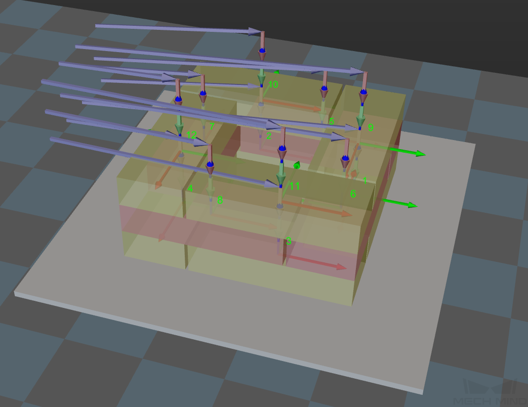
|
Entry Adjust
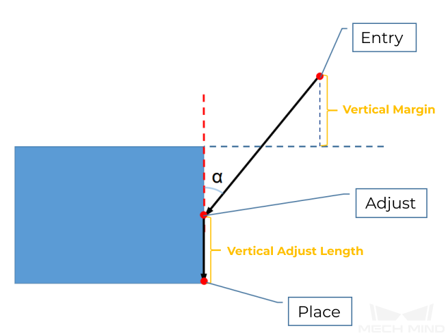
The three parameters together determines the path along which the robot enters the stack area. Adjust the entry path to make the held box approaches the palletized boxes at a specified angle, and then the held box will be placed vertically. If the box is directly placed on the stack in a vertical path, collisions may occur between the robot, held box, and the palletized boxes due to accuracy and other factors.
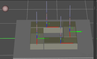
This parameter group determines three positions, as indicated by the red points in the figure, where the box will be moved to when it is placed on the stack. The figure below demonstrates the positions where the box will be moved (in the front view).
Vertical Adjust Length Ratio
| Description |
This parameter affects the “Adjust” position in the figure above. Vertical Adjust Length Ratio = Vertical Adjust Length / Height of the Box |
| Value range |
0–1 |
| Recommended value |
0.5 |
Vertical Margin
| Description |
This parameter affects the “Entry” position in the figure above. The vertical margin is marked in the figure above. |
| Value range |
0–∞; unit: mm. This parameter is used to control the distance above the boxes when the robot approaches the stack. The value should be adjusted according to the on-site situation. |
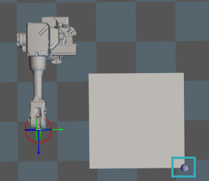
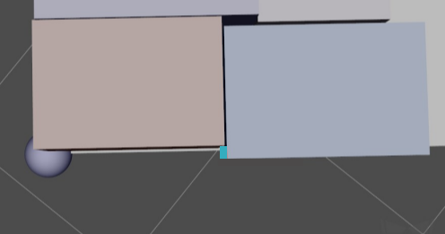
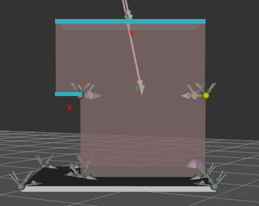
Auto Middle Point
X/Y
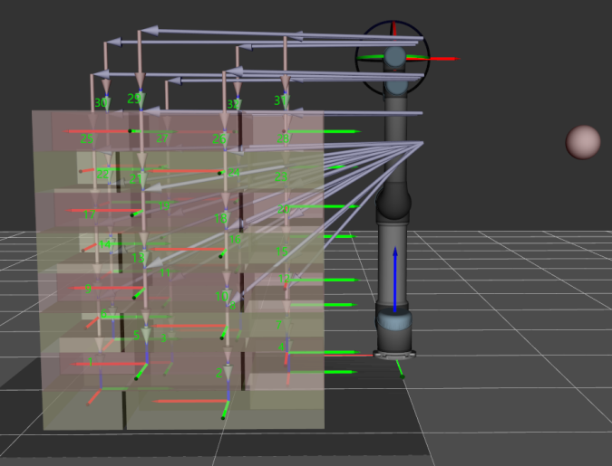
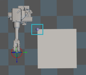
Set the position of the auto middle point (indicated by the pink sphere) in the robot reference frame. Based on this point, center coordinates of stacks with different heights will be calculated.
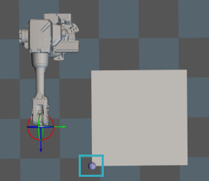
Min Z
When the robot enters the stack area (the path is indicated by the purple arrows), the minimum absolute distance in the Z-direction, i.e., the difference between the Z-direction height and the height of the current layer, as shown in the figure below.
Is Middle Point Traj Vertical
Unselected by default, i.e., the robot will approach the stack from the auto middle point.
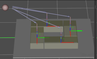
Once this option is selected, the robot will approach the stack from directly above each placing position.
Extended Distance For Entry
For some circumstances, the vacuum gripper is too large, and it may collide with the palletized boxes when approaching the stack. The Extended Distance For Entry can be set to avoid collisions in the approaching process and ensure safety.
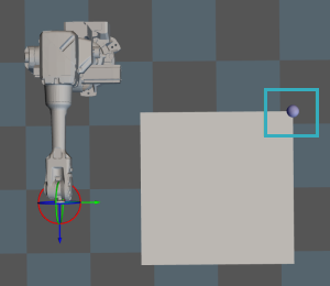
| Auto Middle Point is introduced as a direction reference when the robot approaches the stack, and the point is not an actual waypoint where the robot will move. The auto middle point should be as far away from the pallet as possible. If the auto middle point is too close to the pallet, collisions may occur when palletizing. |
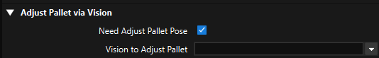
Adjust Pallet via Vision
Adjust the position of the pallet dynamically via the “Vision Look” Step.
Pallet Size
| Pallet X Len |
Set the length of the stack. |
| Pallet Y Len |
Set the width of the stack. |
| Pallet Z Len |
Set the height of the stack. |
| Pallet Z Overflow |
The height of the actual stack can exceed the set height of the stack. |
Example
The Pallet Z Len is 0.6 m, the Pallet Z Overflow is 0.1 m, and the actual allowable maximum height of the stack is 0.6 m + 0.1 m = 0.7 m. Assuming the height of the current stack is 0.45 m, and the height, the remaining height that can be stacked with cartons is 0.7 m - 0.45 m = 0.25 m.
-
If the height of the carton is greater than 0.25 m, it cannot be placed on the stack.
-
If the height of the carton is less than 0.25 m, it can be placed on the stack.
Pallet Type
| Online |
The dimensions of the incoming box are unknown, and the palletizing process of each box will be planned. |
| Offline |
Dimensions of all boxes are known, and the palletizing process of all boxes will be planned at once. |
|
Pallet Setting
Gap Width
The minimum width (mm) of the gap between boxes. To avoid collisions, the measured dimensions of the box should be smaller than the actual dimensions. Recommended value: 10 mm–20 mm
Prior Corner
Description: If a prior corner is selected, the box will be stacked in that corner first. The corner will change along with the pallet pose.
| OO |
The reference corner of the pallet. If the center of the pallet coincides with the origin of the robot reference frame, OO represents the corner in the negative X and negative Y direction of the robot reference frame. |
| OY |
Based on the reference corner OO, the pallet corner that is in the positive Y direction of the robot reference frame. |
| XY |
Based on the reference corner OO, the pallet corner that is in the positive Y and X directions of the robot reference frame. |
| XO |
Based on the reference corner OO, the pallet corner that is in the positive X direction of the robot reference frame. |
OO |
OY |
|
|
XY |
XO |
|
|
Enable Drop
Enable to place the held object by dropping.
Unselected by default, i.e., the object cannot be placed by dropping.
Once this option is selected, when the held carton is a certain distance away from the placing position in the Z-direction, it can be dropped directly.
| Applicable Scenario |
When a shorter carton is placed between two taller ones or the boxes fit each other closely, the box can be placed by dropping to minimize the collision risk. |
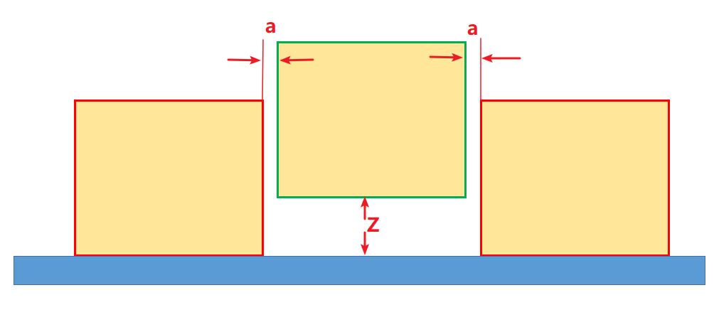
| Drop Height |
Distance in the Z direction at which the object will be dropped. |
| Drop Safe Margin |
The minimum distance between the side of the carton to be placed and its adjacent cartons. |
In the figure below, Z denotes the Drop Height, and a denotes the Drop Safe Margin.
Capture Twice to Update Carton Size
Unselected by default. When the dimensions of the entire object cannot be obtained by just one image-capturing, and a second one is needed, this parameter can be selected.
When the carton is picked via Vision Move and there is no height information of the carton, the height of the carton will be estimated for the planning of the mixed-case palletizing. When the workflow executes to this Step with the “Capture Twice to Update Carton Size” option selected, the height of the box can be obtained by capturing an image for the second time. Then the complete carton dimensions will be used for the planning of mixed-case palletizing.
| This feature can be used in conjunction with the “Update Held Workobject” Step. |
Candidates Limit
Candidate Limit Counts
| Default value |
-1, which indicates that there is no limit on the number of candidate positions. |
| Description |
Used to limit the total number of candidate positions of all boxes, which accelerates the subsequent path planning. If there are 20 candidate positions for planning, if collisions persist and there is no limit on the number of candidate positions, the planning will not stop until all 20 candidate positions are used up. If the Candidate Limit Counts is set to 5, the planning will stop at the 5th attempt if the collision persists. |
Boxes With Tags
Tag on Boundary
Unselected by default, i.e., do not enable this feature.
This feature applies to scenarios where tags are attached to the sides of the boxes and the tags must be exposed to the outside of the stack.
Max Dist From Tag To Pallet Boundary: The maximum distance between the box side where the tag is attached to the edge of the pallet.
Parameters For Find Candidates
Allowed Excess
The allowable width that exceeds the edge of the stack. Recommended value: 0.02 m–0.05 m
Box Exceed Ratio
The maximum ratio of the upper box’s bottom surface area exceeding the surface under it to the total area of its bottom surface.
Layer Height Diff
When the dimensions of the boxes on the top layer are larger than the boxes placed on the lower layer, the larger box is allowed to be placed on a plane with a height difference less than the value of this parameter.
Sampling Rate
The sampling rate for box position planning (sample/meter). The higher the sampling rate, the more accurate the result. However, more calculation speed will be slower. Recommended value: 200, 500, 1000
Corner Free Angle
The angle between the box entry path and the side of an adjacent box on the pallet’s projection plane.
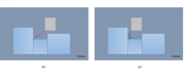
If the set value is too large, a U-shaped blank area may be left after the palletizing. If the set value is too small, collisions with adjacent boxes may occur.
Recommended value: 15°–30°
Enable Mid Point
The mid point here is the midpoint between two corners of the box. When a hollow is formed in the stack, the boxes can be inserted vertically into the hollow.
Safe Radius
When finding the entry angle of a corner, check if a given angle is free of collision on the projected XOY plane within a radius of this value.
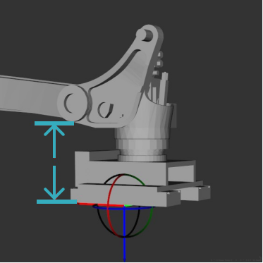
End Effector Dim Z
Height difference between vacuum gripper bottom surface and the bottom surface of the second joint from the bottom of the robot.
Mid Point Safe Gap
When the box is inserted to the candidate positions determined by the mid point, the minimum width of gap between adjacent boxes.
| This parameter will only take effect after Enable Mid Point is selected. |
If the robot motion error and box dimension error is small, this parameter can be set to a value that is smaller than the set Gap Width, which significantly enhances the flexibility or efficiency of stacking when operating in Online mode, especially when placing a box in the middle of the stack. When the Mid Point Safe Gap is greater than the originally set Gap Width, the planning becomes infeasible. The smaller the Mid Point Safe Gap, the more available placing poses.
Scoring Weight
The parameters in this group are all scoring weights that concertedly determine the position on the pallet where the box will be placed.
Adjacent Area Weight
The greater the value, the candidate positions where the box has more contact with the sides of adjacent boxes in the stack are more likely to be selected.
Support Area Weight
The greater the value, the candidate positions where the bottom surface of the box has more contact with the upper surface of the boxes under it (i.e., larger support area) are more likely to be selected.
Base Height Weight
The base height refers to the height difference between the bottom surface of the box to be placed and the pallet in the Z direction. The greater the value, the lower the target position, and the box tends to be placed on a lower plane.
Projected Dist to Corner Weight
The greater the value, the positions with a shorter distance projected on the pallet diagonal to the prior corner are more likely to be selected.
Support Box Num Weight
The greater the value, the positions where more boxes are under the box to be placed are more likely to be selected. The greater the value, the stabler the stack. However, the boxes in the stack may be less compact.
| It is recommended to use multiples as the adjustment intervals during parameter tuning. If you want the box to be placed closer to the prior corner, you can double the value of Projected Dist to Corner Weight and check the result. |
Pallet Setting
Gap Width
The minimum width (mm) of the gap between boxes.
To avoid collisions, the measured dimensions of the box should be smaller than the actual dimensions.
Recommended value: 0.01 m–0.02 m
Prior Corner
Description: If a prior corner is selected, the box will be stacked in that corner first. The corner will change along with the pallet pose.
| OO |
The reference corner of the pallet. If the center of the pallet coincides with the origin of the robot reference frame, OO represents the corner in the negative X and negative Y direction of the robot reference frame. |
| OY |
Based on the reference corner OO, the pallet corner that is in the positive Y direction of the robot reference frame. |
| XY |
Based on the reference corner OO, the pallet corner that is in the positive Y and X directions of the robot reference frame. |
| XO |
Based on the reference corner OO, the pallet corner that is in the positive X direction of the robot reference frame. |
OO |
OY |
|
|
XY |
XO |
|
|
Offline Method
| Best Fit |
This method is applicable to scenarios where the box dimensions vary greatly or the Step is in the Online mode. The pallet pattern eventually planned is not as neat as those planned by using the other three methods. |
| ByStack |
Divide the boxes into different stacks by a specified rule (usually models or dimensions). The boxes that belong to the same stack can be sorted according to a specified rule. The nature of this method is 2-dimensional stacking. |
| ByLayer |
The concept of layer will be introduced. Boxes of the same dimensions will be placed on the same layer. If the layer cannot consist only of boxes of the same dimensions, the layer will be divided into four sections, and each type of box will be placed on an individual section. |
| In Batches |
The palletizing of one SKU can only begin after the palletizing of another SKU is completed. In AGV loading scenarios, this method can effectively reduce the number of times the AGV moves. |
Offline Current Pallet Index
Description: Specify the index of the currently viewed pallet. Default value: -1
Min Box Length
An error message will pop up if the input box length is less than the value of this parameter. When the boxes are relatively small, the planning time for offline mixed-case palletizing will be longer. Setting this parameter can avoid an overly long computation time caused by the mistakenly input box length.