Path Planning Tool
This section introduces the path planning tool and how to use it.
Function
The path planning tool is used to plan a collision-free motion path near the workobject for the robot.
The robot motion path is essentially the motion path of the TCP when the robot completes a task. When the robot moves, the tool may collide with the workobject or scene object. Therefore, to provide various resources and data required for the collision detection and path planning, you need to build a scene that is close to the real scenario, configure the robot tool, and input the vision points and scene point cloud. With the path planning tool, you can input these resources and data to enable the collision detection and path planning. The planned path will be output via the “Path Planning” Step, and therefore the robot can be guided to complete tasks such as picking.
Introduction to Interface
The interface of the path planning tool, as shown below, consists of five parts.
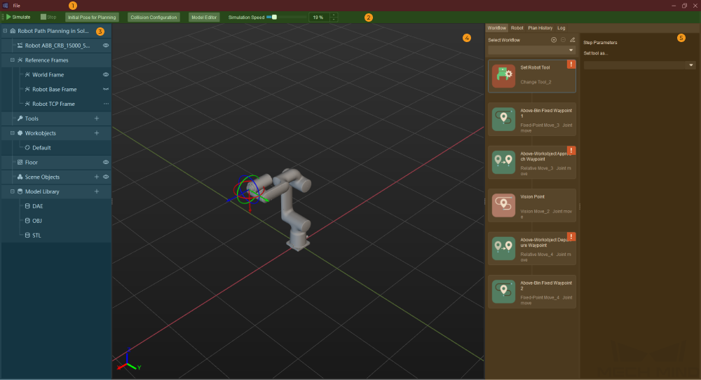
For resetting the settings, saving the settings, and exiting the tool. |
|
For project simulation, setting the initial robot pose, collision detection, and opening the model editor. |
|
For managing the resources used in the project, including tools, workobjects (i.e., the target objects to be picked or processed), and scene objects. |
|
The area where the robot motion path, vision points, point cloud, etc., are visualized during the simulation. |
|
For configuring the workflow and robot pose and checking the plan history and log. |
Basic Procedures
The basic procedures for using the path planning tool are as follows:
Configure Project Resources
Resources include the robot, tools, workobjects, and scene objects, which are fundamental to a project.
In the Resources panel, you can do the following:
-
Import tool models and scene object models which will be used for the collision detection.
-
Set the symmetry of the tool, symmetry of the workobject, and picking relaxation, which may lead to more alternative waypoints and a more flexible path planning.
| Configuration Entry | Description |
|---|---|
Tools |
Tools, such as grippers and suction cups, are specially designed mechanical devices attached to the flange of the robot to perform various tasks.
|
Workobjects |
Workobjects refer to the objects on which the tool performs tasks, such as cartons, metal parts, and parts to be glued or welded.
|
Floor |
The simulated floor based on the real scenario. The default floor plane is at the same level where the bottom of the robot base is located. You should adjust the height of the floor according to the actual situation.
|
Scene Objects |
Scene objects, usually including the safety fence, picking bin, tray, camera, and camera stand, refer to objects in the real scenarios where the robot performs various tasks.
|
Build the Workflow
You can build a workflow, i.e. a robot motion control program in the form of a flowchart, in the Workflow tab. You can modify the default workflow to plan a feasible robot motion path for picking.
A workflow usually includes the following Steps:
-
Set Robot Tool
This Step is used to select a tool. Click the Step and click
 in the Step Parameters panel to select the corresponding tool configured in the Project Resources panel.
 -
Above-Bin Fixed Waypoint 1
This Step sets a waypoint where the robot reaches before it approaches the workobject. Please refer to Fixed-Point Move for detailed parameter description.
-
Above-Workobject Approach Waypoint
This Step sets a waypoint above the workobject when the robot approaches the workobject. Please refer to Relative Move for detailed parameter description.
-
Vision Point
This Step specifies the vision point. Please refer to Vision Move for detailed parameter description.
-
Above-Workobject Departure Waypoint
This Step sets a waypoint above the workobject when the robot leaves the workobject. Please refer to Relative Move for detailed parameter description.
-
Above-Bin Fixed Waypoint 2
This Step sets a waypoint where the robot reaches after it leaves the workobject. Please refer to Fixed-Point Move for detailed parameter description.
If the above waypoints cannot meet the actual requirement, you can add waypoints by adding “Fixed-Point Move” or “Relative Move” Steps to the workflow.
-
To add a waypoint, move the mouse cursor to the line connecting the Steps, and click
 , and then select the Step you want to add.
 -
To delete a Step, right-click the Step and then click Delete. You can also delete it by clicking the Step and then press the Delete key.
In addition, the same resources can be used in different workflows which result in different planned paths. In scenarios where the project involves different workobjects or bins, you may need to add multiple workflows and change the workflow by switching the parameter recipe.
-
Click ![]() , enter a workflow name in the pop-up window, and then click OK to create a new workflow.
, enter a workflow name in the pop-up window, and then click OK to create a new workflow.
Collision Configuration
Collision configuration is used to detect and avoid possible collisions. By default, collisions between any two of the robot, robot tool, and scene objects will be detected. Once Enable collision detection with point cloud is enabled, the collision between the input point cloud and the robot tool will be detected.
-
Click Collision Configuration on the toolbar and configure the following parameters according to the allowable level of collision in the project.
- Point cloud cube side length
-
In the collision detection, cubes with each point in the point cloud as their centers will be generated. Detecting the collision between the tool and the point cloud is actually detecting the collision between the tool and the cubes. The longer the cube’s side length, the higher the possibility of the tool colliding with the point cloud, and the larger the collision volume.
- Tool-point cloud collision volume threshold
-
When the collision volume between the tool and the point cloud is above the set threshold, it will be assumed that a collision occurs; otherwise, it will be assumed that no collision occurs.
- Point cloud collision record
-
-
Record: The plan history will record the positions and quantity of the point clouds where collisions occur. When the user views the planning history, the recorded point cloud will be highlighted in the 3D simulation area. Recording affects the execution speed.
-
Do not record: The user will not be able to trace which part of the point cloud was involved in collision(s) in the plan history. On the other side, the execution speed is higher when not recording the point cloud in collision.
-
-
After you finish the configuration, click OK.
Simulate and Debug
After you finish the above configurations, you can control the simulated robot to test whether there is a collision or other error in the planned path.
|
-
Click Simulate on the toolbar.
-
If an error occurs during the simulation, such as a collision or unreachable waypoint occurs, check the error messages in Plan History and Log, and therefore locate the error quickly and then improve the project by adjusting the resources, workflow, and collision configuration.
-
If no error occurs in the simulation, click to save the configurations.
After you finish using the path planning tool, click to close the path planning tool. Then go back to the Step Parameters panel in the main interface of Mech-Vision, and select the workflow you created in the drop-down list.