Model Editor
This section covers the introduction of Model Editor and the user guide.
Introduction
The collision models of tools used in Mech-Viz should be OBJ models that are composed entirely of convex polyhedra (convex hulls). With the Model Editor, you can create convex hulls on the original tool model and convert the model file to OBJ format. Besides, you can use the Model Editor to re-create the reference frame of the tool model and export the model file to STL format.
Supported File Formats
-
Imported reference models: STP, STEP, STL, and OBJ
-
Exported reference models: STL
-
Exported convex polyhedral models: OBJ
Interface Introduction
The interface of model editor consists of the following 5 main parts.
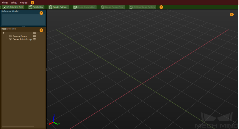
Please refer to corresponding links for detailed information.
| Menu Bar | Provides functions as importing and exporting the model file, editing, and opening the user guide |
|---|---|
Provides basic tools for the Model Editor |
|
Displays the imported reference model files |
|
For viewing and editing geometric solids, convex hulls and center points |
|
For viewing and editing models |
Create Convex Polyhedral Models
The steps to convert STL models, STP models, STEP models, and illegal OBJ models to OBJ models that are composed entirely of convex polyhedra are as follows.
“Create the Reference Frame” and “Create Convex Polyhedra” Demo Video:
Import Reference Model
Supported file formats of imported reference models include STP, STEP, STL, and OBJ.
Follow either of these steps to import the reference model.
-
Click and select the reference model file in the file selection window.
-
Drag and drop the reference model file to the interface of the Model Editor.
Select the unit according to the actual dimensions of the model in the pop-up window, and click OK.
| If an error message “Failed to load the model” pops up, please refer to Determine Whether the STEP/STP File Is Eligible to check the model file. |
Create the Reference Frame
If the world reference frame in the Model Editor does not coincide with the actual installation reference frame of the model, you should re-create the reference frame. If the world coordinate system coincides with the reference frame of the model, you can skip this topic and continue to read the Create Convex Polyhedra.
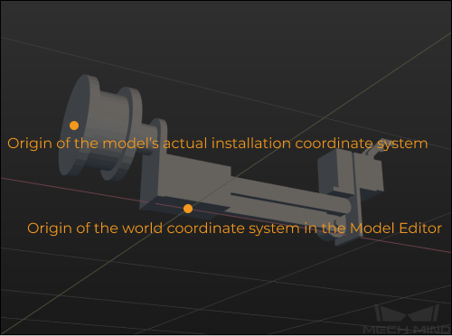
You will need to set a new origin or adjust the direction of the axis to create the reference frame.
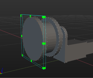
Set a New Origin
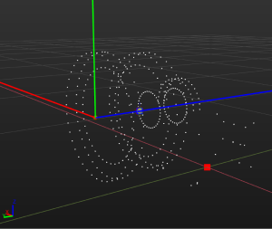
You can select the vertices on the model with a cuboid-shaped selection frame, and use these vertices as reference points to generate a “center point”, which can be set as the origin of the reference frame. You can also select a vertex of the model as the origin.
The following steps shows how to set a “center point” as the new origin.
Select the model name in the “Reference Model” panel.
|
|
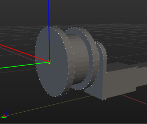
Click Create Center Point, and the point will be used as the origin of the reference frame. |
|
Click Set Frame.
|
|

If one of the vertices of the model you use can be used as the origin of the reference frame, please follow the steps below:
-
Click Set Frame.
-
Click Select on the right of Coordinate Origin in the Coordinate Parameters panel.
-
Select a vertex of the model in the 3D editing workspace.
|
Adjust the Axis Direction
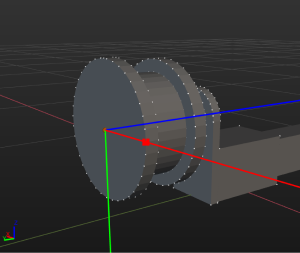
If the direction of each axis of the newly-created reference frame is correct, you do not need to adjust the direction of the axis. If not, adjust the direction of each axis by using the center point or model vertex. Please follow the steps below.
Unselect Select center point.
|
|
Select Select center point in the Coordinate Parameters panel on the right.
|
|
Unselect Select center point.
|
|
Click Confirm.
|
|
Create Convex Polyhedra
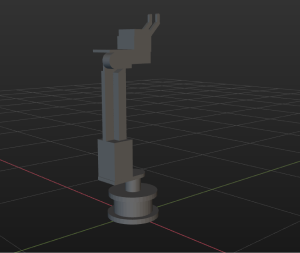
The collision models of tools used in Mech-Viz should be OBJ models that are composed entirely of convex polyhedra, and a convex polyhedral model should be created based on the reference model. The final convex polyhedral model should be composed entirely of convex polyhedra and reflect the shape of the original reference model as accurately as possible.
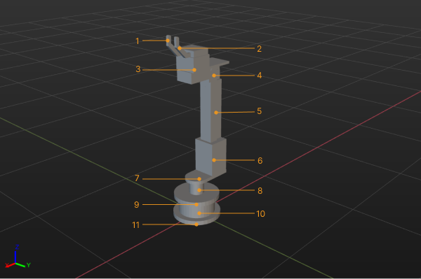
Do not use the 3D selection tool to cover the whole model to create a convex hull. It is recommended to segment the model into multiple parts according to its structure, and use the 3D selection frame to select each part and create convex hulls separately. For example, the model in the figure below can be segmented into 11 parts.
The steps to create a convex polyhedral model are as follows:
-
Select the model name in the “Reference Model” panel, and click 3D Selection Tool.
-
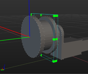
Adjust the cuboid-shaped selection frame to cover the vertices on the part to be processed, and click Create Convex Hull.
-
Repeat step 2 until all 11 parts of the model are covered by convex hulls.
-
Click
 on the left of the reference model name to view the convex polyhedral model.
|
Save the Project File
To facilitate re-editing of the model, you can follow these steps to save the model to M3D format.
-
Click .
-
Specify a save path and enter a file name.
-
Click Save.
Export the Model after Editing
Follow these steps to save the edited model to OBJ format.
-
Click .
-
Specify a save path and enter a file name.
-
Click Save.
Once the model is exported successfully, you can add the model to . Then you can set the corresponding collision model of end tools in .
3D Selection Tool User Guide
|
Once you select the name of the reference model, click |
Click 3D Selection Tool, and the cuboid-shaped selection frame can be used to select the vertices on the model. You can use either of the following methods to adjust the dimensions and position of the cuboid-shaped selection frame.
-
Adjust in the 3D editing workspace
-
While pressing and holding the Ctrl key, click and hold the left button on the mouse and drag the vertex of the selection frame to adjust its dimensions.
-
While pressing and holding the Ctrl key, click and hold the left button on the mouse and drag the surface of the selection frame to adjust its position.
-
-
Adjust in the 3D Selection Tool panel on the right
-
Adjust the Dimensions parameters to adjust the dimensions of the selection frame.
-
Adjust the Center and Rotation parameters to adjust the position of the selection frame.
-
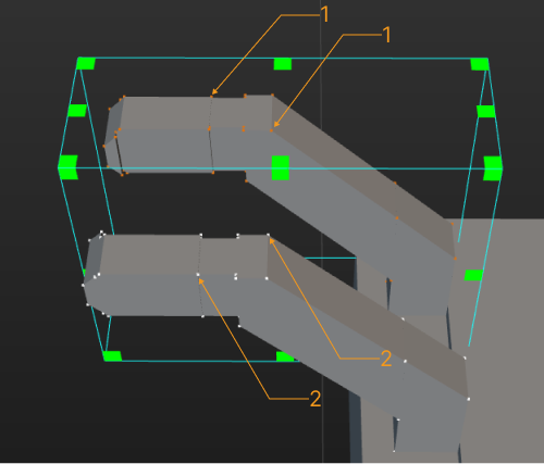
1 Selected model vertices; 2 Unselected model vertices
Create a Box or Cylinder
Besides using the 3D selection tool to create convex hulls, you can also create cuboids or cylinders to cover parts of the model.
Follow these steps to create a box. (The steps to create a cylinder are similar.)
-
Click Create Box.
-
Name the object in the pop-up window, and roughly modify the dimensions of the object, and then click OK.
-
By default, the center of the newly created box coincides with the origin of the reference frame in the 3D editing workspace. While pressing and holding the Ctrl key, click and hold the left button on the mouse and drag the dragger to move the box to the part to be covered.
-
Double-click the cuboid model, adjust the dimensions and position in the Convex Object Configuration window to make the frame cover the part as accurately as possible.
Convert the Display Model File to STL Format
Convert the model file in STP or STEP formats to STL format that is supported by the software.
-
Follow either of these steps to import the model to be processed.
-
Click and select the reference model file in the file selection window.
-
Drag and drop the reference model file to the interface of the Model Editor.
-
-
Click .
-
In the Export Model window, specify a save path and enter a file name, and then click Save.
Once the model is exported successfully, you can add the model to . Then you can set it as a visualization model for a tool in , or set it as a visualization model for a scene object in .