Complete Calibration for Truss Robots
This how-to guide introduces how to complete the hand-eye calibration for truss robots.
|
For the concepts related to the hand-eye calibration for truss robots and the usage of the extrinsic parameter file, please refer to the section Explanation of the Calibration for Truss Robots. |
Preparation before Calibration
Before hand-eye calibration, you need to finish the following preparations:
-
Construct the Mech-Mind Vision System.
-
Prepare the materials required for calibration.
-
Adjust the effect of calibration board’s point cloud.
Construct the Mech-Mind Vision System
Construct the Mech-Mind Vision System by referring to the section Construct Mech-Mind Vision System.
You need to use Mech-Eye Viewer, Mech-Center, Mech-Vision and Mech-Viz during hand-eye calibration. Please ensure that they have been installed and are running the latest versions.
Prepare the Materials Required for Calibration
The hand-eye calibration for truss robots needs to use the following materials:
-
Calibration board
-
Sharp tip
-
Tape measure
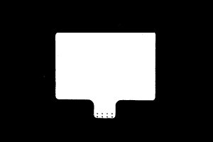
Please prepare the calibration board according to the following requirements:
-
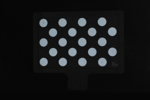
Ensure that the circles of the calibration board are clearly visible and without obvious scratches, and the board does not suffer from deformations.
-
In the calibration for truss robot scenario, please place the calibration board in the center of the object plane, where target objects are to be placed.
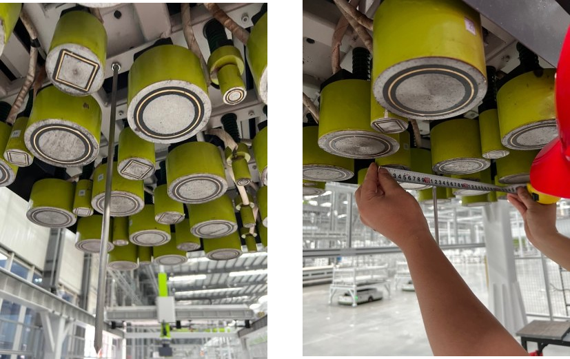
The sharp tip should be mounted on the center of the truss robot’s gripper. The tape measure is used to measure the deviation from the sharp point to the center of the robot flange in X, Y, and Z directions.
Adjust the Effect of Calibration Board’s Point Cloud
-
Open Mech-Eye Viewer to adjust camera parameters.
-
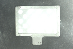
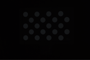
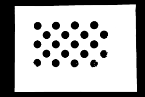
Adjust 2D parameters to make sure that the 2D image of the calibration board is clear and neither overexposed nor underexposed.
-
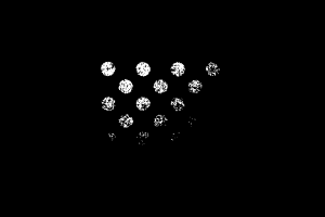
Adjust 3D parameters to make sure that the point clouds of the circles on the calibration board are complete and have clear contours. It is recommended to set Point Cloud Smoothing and Outlier Removal to Normal in the Point Cloud Processing section to reduce the point cloud fluctuation range.
If the on-site ambient lights are not ideal and affects the quality of 2D images and point clouds, you can use shading or supplemental light to improve the lighting conditions.
-
Make sure that the images and point cloud of the calibration board are up to standard after completing preceding steps.
Normal Overexposed Underexposed 2D image
Point cloud
Pre-calibration Configuration
-
Open Mech-Vision, and click the Camera Calibration (Standard) button in the toolbar. The Configuration before Calibration window will be prompted.
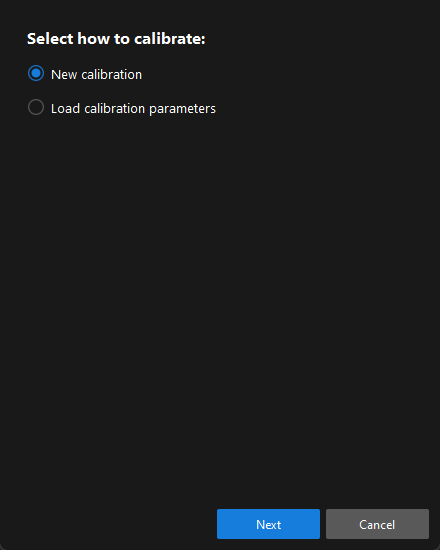
-
In the Select how to calibrate window, select the New calibration radio button, and then click the Next button.
-
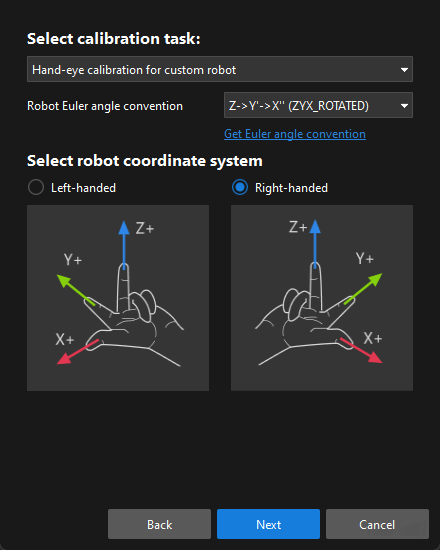
In the Select calibration task window, select Hand-eye calibration for custom robot from the drop-down list box, specify the Robot Euler angle convention parameter, select the robot coordinate system type, and then click the Next button.
-
You can determine robot coordinate system type according to the section Left- and Right-handed Coordinate Systems. If the truss robot uses the left-handed coordinate system, you just need to select Left-handed here.
-
When the vision system communicates with the robot, the communication module will automatically transform the coordinate system for the sent and received poses. When the communication module receives the robot pose from the robot side, it transforms the robot pose in the left-handed coordinate system to the one in the right-handed coordinate system; when it sends the pose output by the software to the robot side, it transforms the robot pose in the right-handed coordinate system to the one in the left-handed coordinate system.
-
When the robot flange pose is required to be input during the calibration procedure, you need to take the inverse of the Y-axis value first.
-
-
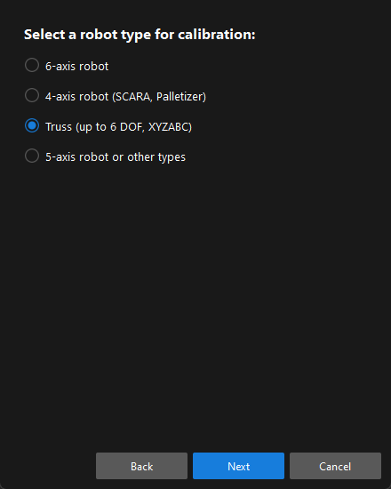
In the Select a robot type for calibration window, select the Truss (up to 6 DOF, XYZABC), and then click the Next button.
-
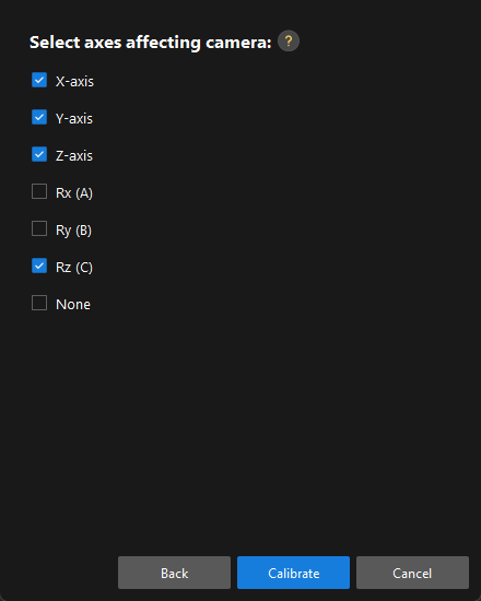
In the Select axes affecting camera window, select the axes as required (such as X-axis, Y-axis, Z-axis, and Rz), and then click the Calibrate button.
Calibration Procedure
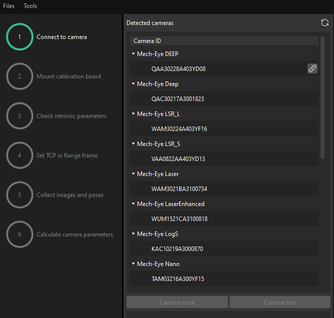
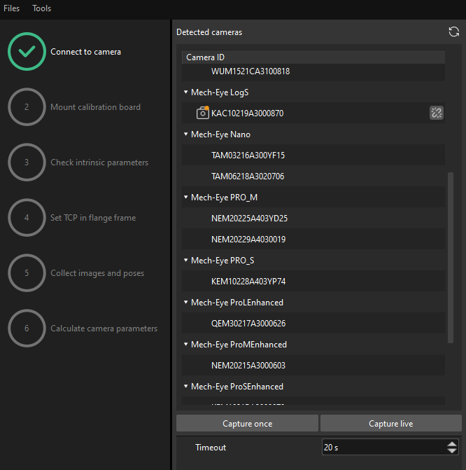
Connect to the Camera
-
In the Connect to Camera step, find the camera to connect in the Detected Cameras list, and click
 .
.
-
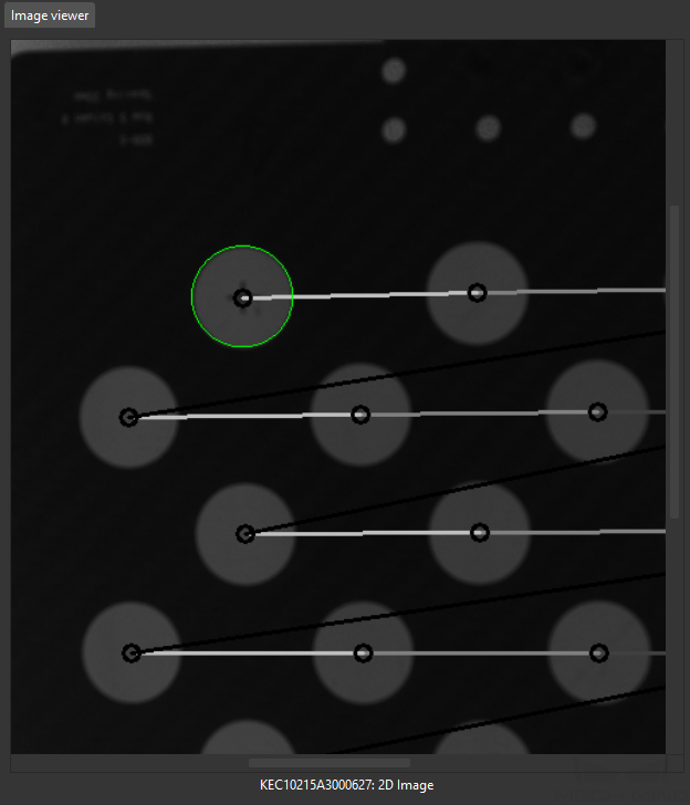
After the camera is connected, click the Capture once or Capture live button.
-
In the right Image viewer panel, ensure that the captured 2D image and depth map meet the calibration requirements and click the Next button on the bottom bar.
If the captured image does not meet the calibration requirements, you need to open the Mech-Eye Viewer software to adjust the 2D and 3D exposure parameters and re-capture images.
Mount the Calibration Board
-
In the Mount calibration board step, select the Standard radio button and select the calibration board model according to its model nameplate in the 1. Select calibration board type area.
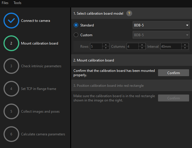
-
Make sure that the calibration board has been placed to the plane of the workobject, and then click the Confirm button in the 2. Mount calibration board area.
-
Confirm that the calibration board is in the center of the camera’s field of view (the red rectangle), and then click the Confirm button in the 3. Position calibration board into red rectangle area.
-
After all the operations related to the calibration board are completed, click the Next button on the bottom bar.
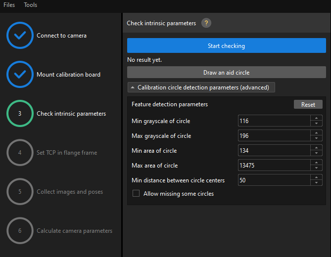
Check Intrinsic Parameters
-
In the Check intrinsic parameters step, click the Start checking button.
-
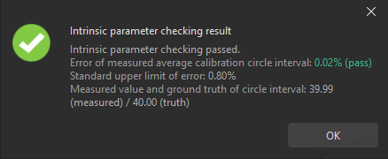
Confirm the results of the camera intrinsic parameter check.
-
If the camera intrinsic parameter check passes, click the OK button and then click the Next button on the bottom bar.
-
If the camera intrinsic parameter check fails, adjust detection parameters by drawing aid circles or manually adjusting the calibration circle detection parameters, and then click the Check again button.
-
Draw an Aid Circle
-
To draw an aid circle, click the Draw an aid circle button.
-
In the right Image viewer panel, right-click the calibration board image and clear the Fit to window checkbox, and press the Ctrl key and drag the roller to adjust the image to a suitable size.
-
Move the mouse pointer to the cross center point of the calibration circle, press the left mouse button and make the aid circle completely include the calibration circle and then release it.
-
Click the Check again button, and confirm that the camera intrinsic parameter check passes.
Manually Adjust Detection Parameters
To manually adjust the detection parameters, click Calibration circle detection parameters (advanced) and change the values of detection parameters accordingly.
If the calibration circles are still not detected, please adjust the camera settings according to the on-site operating conditions.
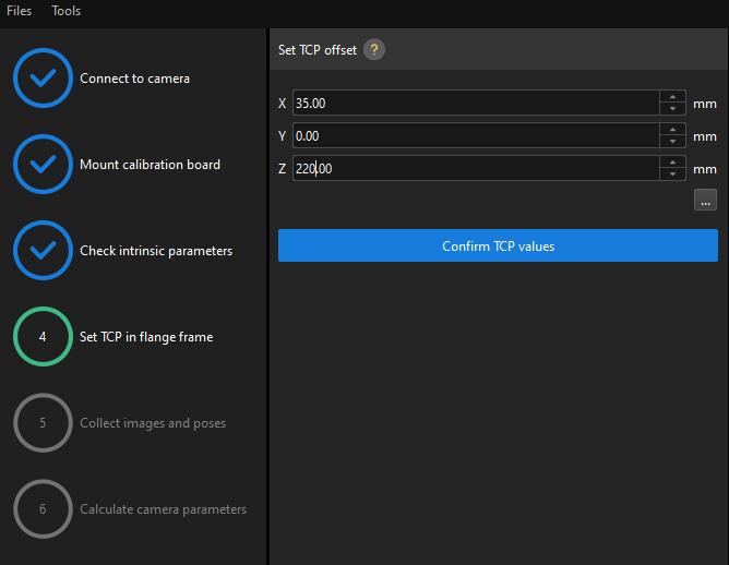
Set TCP in Flange Frame
|
Before this step, use the tape measure to measure the deviation (in mm) from the sharp point to the center of the flange in X, Y, and Z directions. |
In the Set TCP in flange frame step, enter the deviation values in X, Y, and Z directions in the X, Y and Z text boxes, Click the Confirm TCP values button and then click the Next button on the bottom bar.
|
If the truss robot uses the left-handed coordinate system, you need to take the inverse of the deviation value in the Y direction before entering it. |
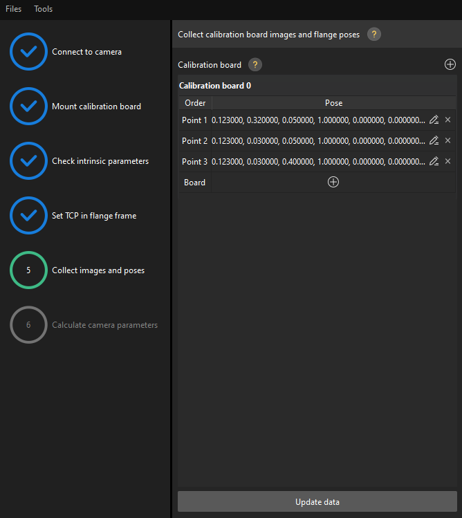
Collect Images and Poses
-
Control the truss robot to let its end tip touch the cross center point of point 1 on the calibration board, and record the robot flange pose in the teach pendant.
-
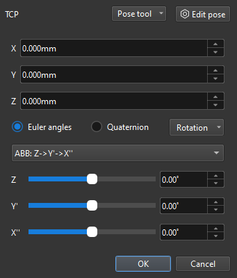
In the Collect Images and Poses Step, click the
 button of point 1, and enter the robot flange pose in the prompted Input Flange Pose of Robot dialog box, and then click OK button.
If the truss robot uses the left-handed coordinate system, you need to take the inverse of the Y-axis value before entering the robot flange pose.
-
Repeat the preceding steps, and let the end tip touch the cross center points of point 2 and point 3, and enter robot flange poses.
-
Click the
button of the current calibration board to capture the images of it. -
Click the Update data button and then click the Next button on the bottom bar.
-
The calibration program requires that at least three points not in a line should be touched for calculating extrinsic parameters.
-
If the truss robot lacks a degree of freedom in a certain direction (for example, in the Y direction), you can add the poses of multiple calibration boards. First, adjust the direction of the calibration board so that the sharp point can touch two points on the calibration board, and at the same time input the pose of the robot flange and collect the image of the calibration board. Then raise (or lower) the calibration board in the Z direction, and again touch the points on the calibration board along the X direction, and at the same time input the pose of the robot flange and collect the image of the calibration board. Make sure that the new position of the calibration board is significantly different from the pervious one.
-
Calculate Camera Parameters
-
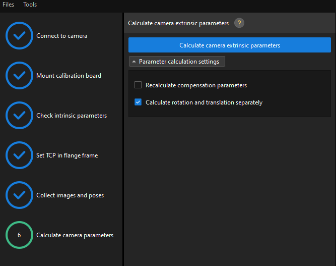
In the Calculate camera parameters window, click the Calculate camera extrinsic parameters button.
-
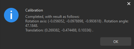
In the prompted window indicating calibration success, click the OK button.
-
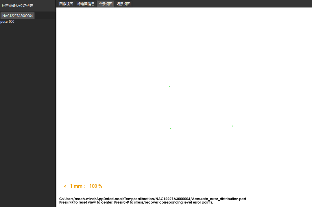
View the calibration error of the point cloud in the right Point cloud viewer panel.
The error point cloud shows the deviation between the calculated value and the actual value of the circles on the calibration board. -
Confirm that the calibration accuracy meets the project requirements.
Find the error value with the 100% percentage to get the rough calibration accuracy. For example, the calibration accuracy in the following figure is within 1 mm.
If you want to enhance the calibration accuracy, please refer to the section Calibration Result Check and Analysis.
Validate and Save the Calibration Result
You can check calibration results roughly by inspecting the shift of the calibration board’s point cloud (to be specific, the crosshair of a calibration circle on the board) in reference to a fixed point in Scene Viewer. To do so, follow these steps:
-
Place the calibration board on a fixed position.
-
Open Mech-Viz, add a fixed point, and make sure that this point coincides with the crosshair of a calibration circle on the calibration board.
-
Find the “Fixed-Point Move” Step from the Step library and then drag it to the graphical programming workspace.
-
Select this Step, set the Waypoint type parameter to “Workobject pose” on the parameter panel, adjust the X, Y and Z values of the pose to make this point coincide with the crosshair of a calibration circle on the calibration board.
-
-
Control the robot to change the pose of the camera for several times, and click the Recalculate camera extrinsic parameters button in the Calculate camera parameters step of the calibration process. This operation will trigger the camera to capture images.
-
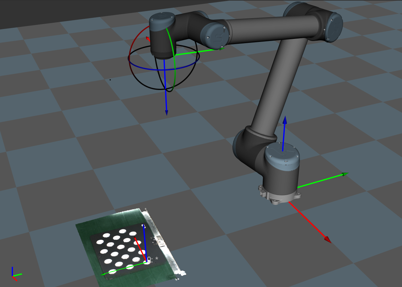
Check whether the calibration board’s point cloud has a significant shift in reference to the fixed point in Scene viewer.
If the calibration board’s point cloud does not have a significant shift, the calibration is successful.
|
-
Click the Save button on the bottom bar. In the prompted Save Calibration Files dialog box, click the OK button. The camera calibration result will be automatically saved in the “calibration” directory of the project.
Till now, the calibration process is completed.
So far, the hand-eye calibration for the truss robot is completed.