Project Construction Framework
In this section, a simple machine tending project will be constructed as an example to show you the framework of project construction.
The 3D matching algorithm will be used in the project to compute the pick points on the workpieces.
Project Framework
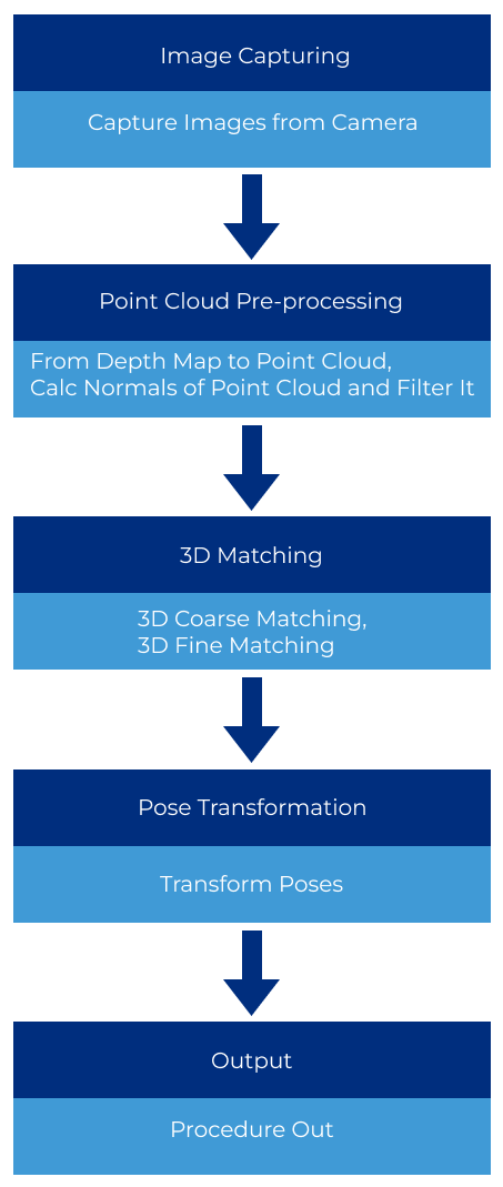
The Steps used in this project include Capture Images from Camera, From Depth Map to Point Cloud, Calc Normals of Point Cloud and Filter it, 3D Coarse Matching, 3D Fine Matching, Transform Poses, and Procedure Out.
Steps related to 3D matching is the core of the project as they are used to obtain the pick point of the object.
Create and Save the Project
Please refer to Create and Save Project for detailed instructions.
Add Steps
After having an overview of the project framework and creating the project, you can start to add Steps and construct the project.
-
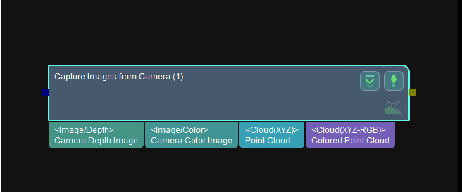
Add the Capture Images from Camera Step, which is used to trigger the camera to capture images and obtain color images and depth maps.
Before adding this Step, please make sure that the camera has been mounted properly and has been connected to the IPC successfully. In addition, an image capturing test has been done and the hand-eye calibration has been carried out.
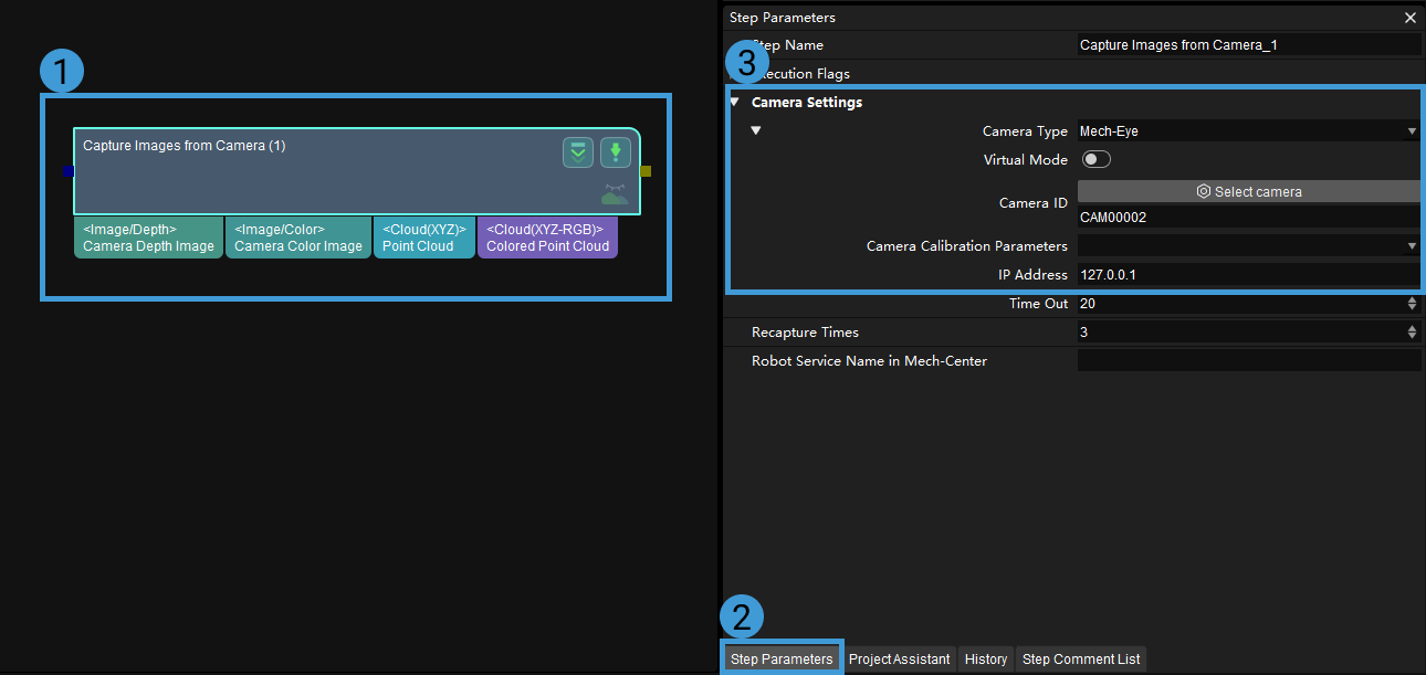
After adding the Step, select it and click the Step Parameters tab. Then you can configure the parameters related to the camera, including Camera Type, Camera ID, Camera Calibration Parameters, and the IP Address.
-
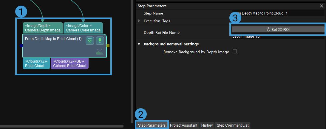
Add the From Depth Map to Point Cloud Step, which is used to convert the depth maps to point clouds. This Step should follow the Step Capture Images from Camera. Connect the output port for depth maps of Capture Images from Camera to the input port for depth maps of From Depth Map to Point Cloud.
Connect the input and output ports for color images in the same way. Keep the default settings on the parameters when running the project.
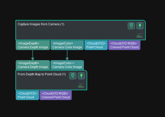
The two Steps should be connected with each other as shown in the figure above. Then you have added the From Depth Map to Point Cloud Step and input the data you need successfully.
After adding the Step, a 2D ROI should be selected to avoid interference from background and outliers and therefore reduce the processing time of subsequent Steps. Select the Step, click the Step Parameters tab, and then click Set 2D ROI. Please refer to Set ROI for detailed instructions on setting 2D ROI.
-
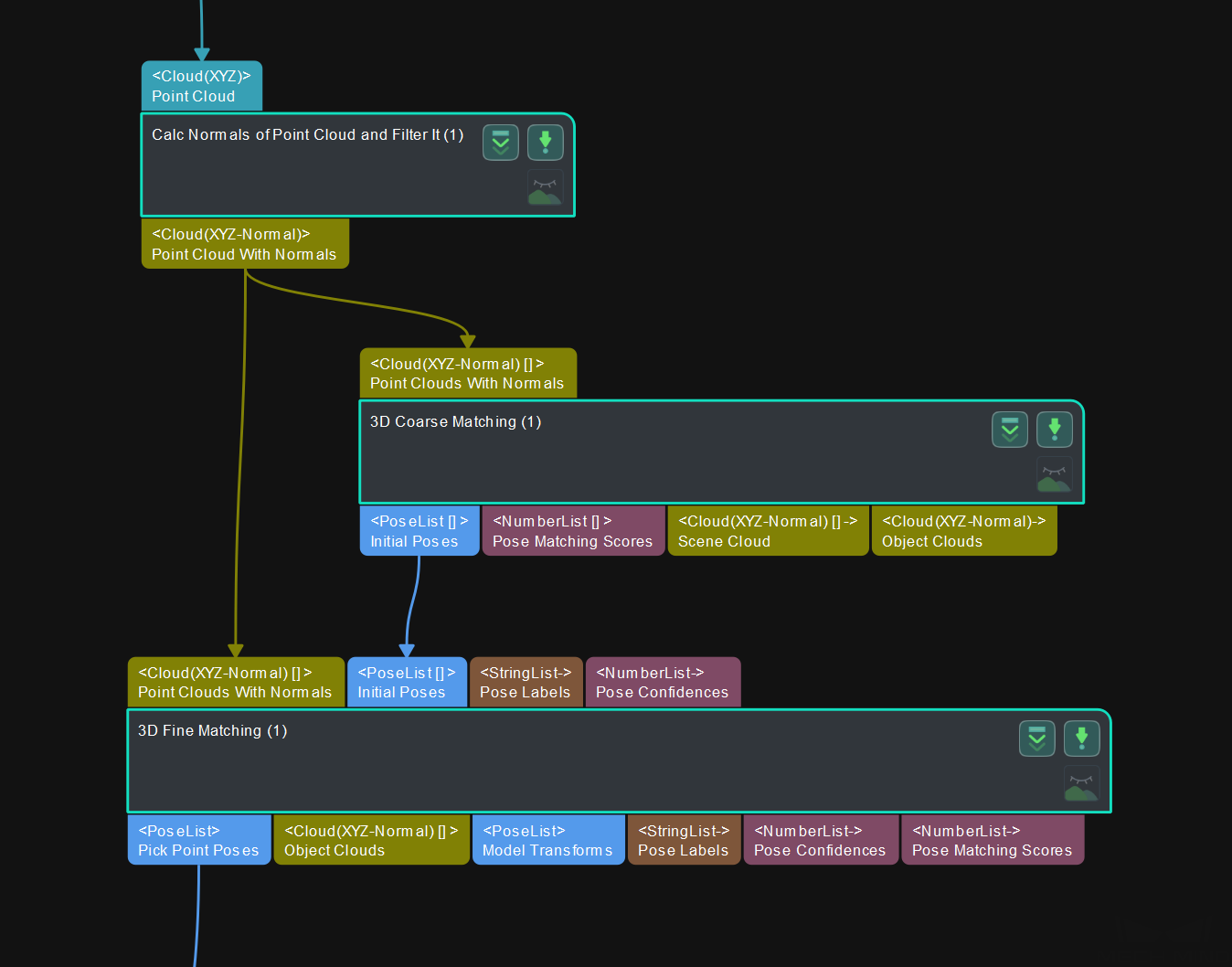
Add the Calc Normals of Point Cloud and Filter it Step, which is used to compute normals of each point in the input point cloud. Therefore, the point cloud that only contains position information can be converted to point cloud with normals. This Step will follow the From Depth Map to Point Cloud Step. Connect the output port for point cloud of From Depth Map to Point Cloud to the input port for point cloud of Calc Normals of Point Cloud and Filter it.
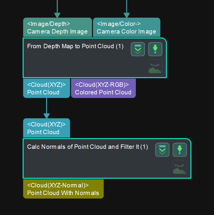
After obtaining point cloud with normals, the 3D Coarse Matching and 3D Fine Matching Steps can be used to match the input point cloud with the point cloud model.
-
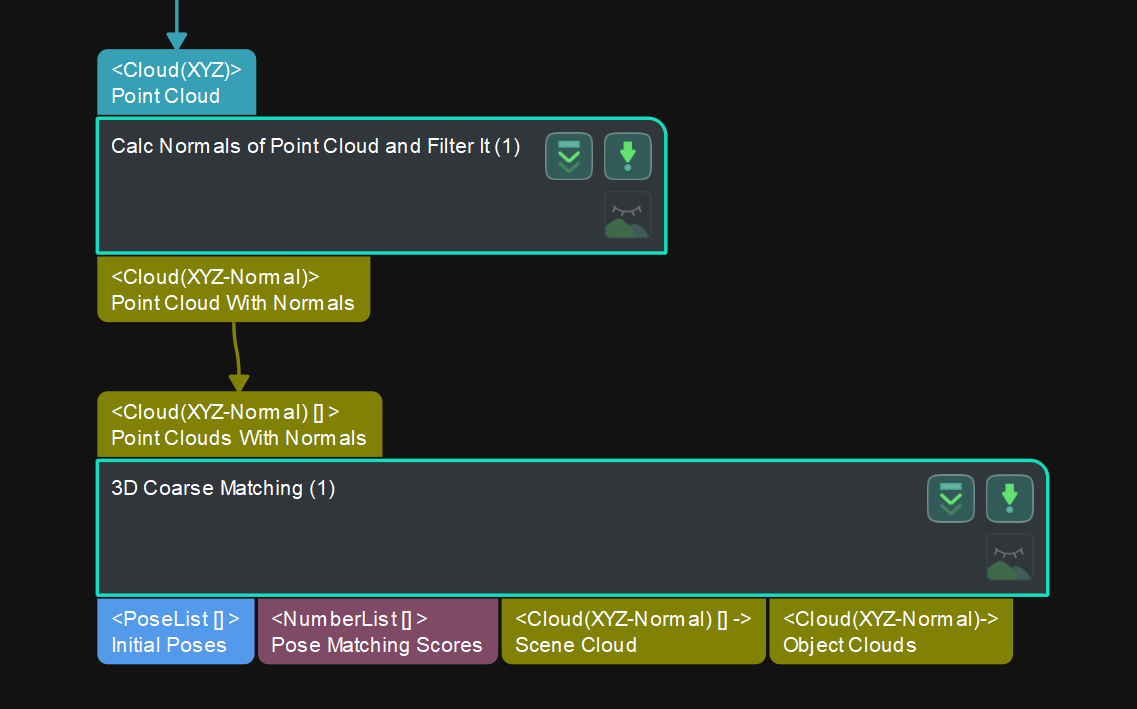
Add the 3D Coarse Matching Step, which is used to coarsely match the point cloud model with the input point cloud with normals and then generate the corresponding geometric center and pick point according to the matching result. This Step should follow the Calc Normals of Point Cloud and Filter it Step. Connect the output port for point cloud with normals of Calc Normals of Point Cloud and Filter it to the input port for point cloud with normals of 3D Coarse Matching.
After connecting the Steps, please input the point cloud model file and geometric center file that have been made before. Select the 3D Coarse Matching Step first, and then click the Step Parameters tab. Click
 in the Step Parameters panel and then choose the Model File and Geo Center Point File to input.
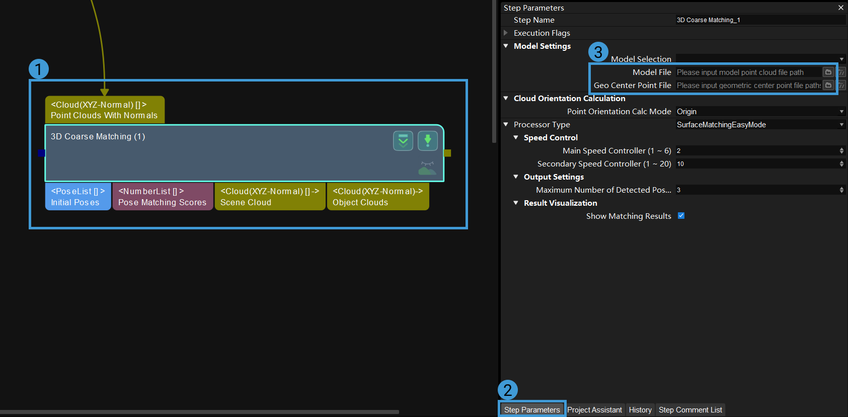
Please refer to Matching Model and Pick Point Editor for instructions on making point cloud model file and geometric center file.
-
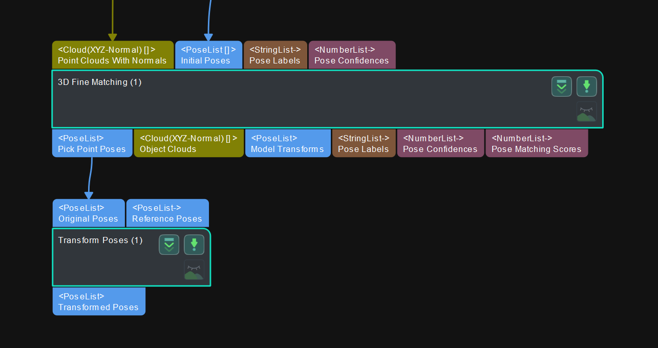
Add the 3D Fine Matching Step, which is used to fine-tune the matching result from 3D Coarse Matching and generate a more precise geometric center and pick point. This Step should follow the 3D Coarse Matching Step. Connect the output port for point cloud with normals of Calc Normals of Point Cloud and Filter it to the input port for point cloud with normals of 3D Fine Matching, and connect the output port for initial poses of 3D Coarse Matching to the input port for initial poses of 3D Fine Matching.
After obtaining precise poses via 3D Fine Matching, the obtained poses need to be transformed.
The method to input Model File and Geo Center Point File in 3D Fine Matching is the same as that of 3D Coarse Matching.
-
Add the Transform Poses Step, which is used to convert the input poses in the camera frame of reference into poses in the robot frame of reference. This Step should follow the 3D Fine Matching Step. Connect the output port for pick point poses of 3D Fine Matching to the input port for original poses of Transform Poses. Keep the default settings on the parameters when running the project.
-
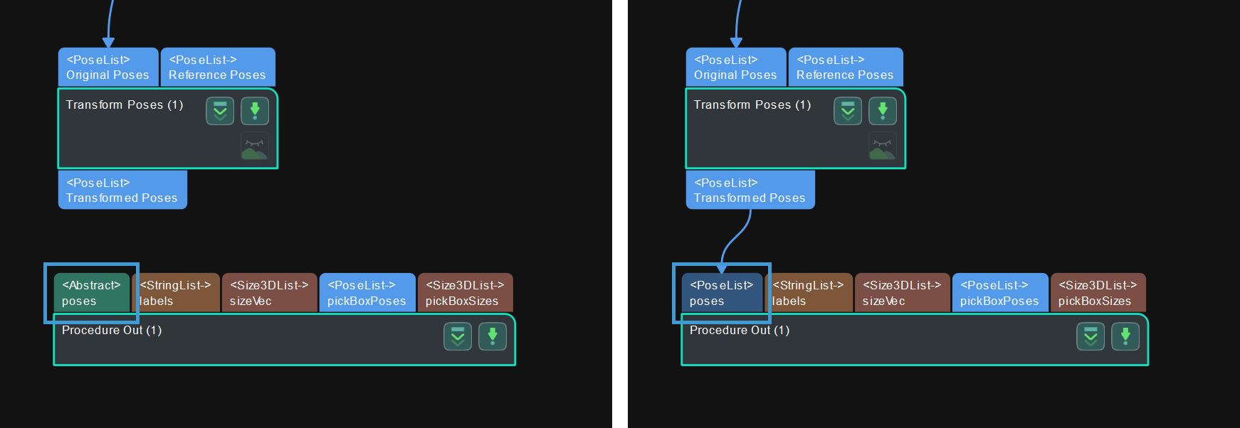
Add the Procedure Out Step, which is used to send the input data to Mech-Center, which will send the data to relevant software and devices. This Step should follow the Transform Poses Step. Connect the output port for transformed poses of Transform Poses to the input port for poses (the first port on the left) of Procedure Out. The <Abstract> poses will turn to <PoseList> poses, as shown in the figure below .
Now you have completed constructing a simple matching project. You can use the shortcut Ctrl + S or go to to save the project.
|
After adding and connecting all the Steps, you can arrange the layout of the Steps to make the logic of the data flow clearer. There are three ways to arrange the layout of the Steps:
|
After the construction of the project is completed, you can start to run and debug the project.