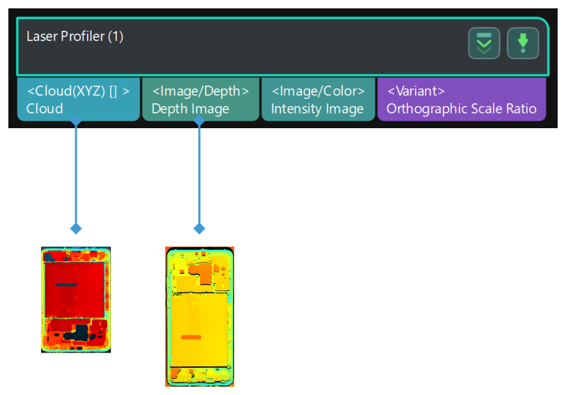
Laser Profiler
Function
This Step allows Mech-Vision to control a laser profiler to scan and obtain the scan data.
|
Currently, only Mech-Eye 3D Laser Profiler and SSZN 3D cameras can be controlled by this Step. |
Usage Scenario
This Step is used as the first Step to input scan data of a laser profiler to the Mech-Vision project. This Step is suitable for high-accuracy inspection and measurement applications in industries include 3C, EV battery, automobile, and home electronics.
Parameters
Please select the camera in use in the Camera type parameter. The available options are LNXCamera (default) and SSZNCamera.
-
If you are using Mech-Eye 3D Laser Profiler, please select LNXCamera.
-
If you are using an SSZN 3D camera, please select SSZNCamera.
LNXCamera
When using the LNX series of Mech-Eye 3D Laser Profiler, the following parameters are available.
- IP
-
Description: This parameter is used to set the IP address of the camera to be connected.
Instruction: Click Open an Editor and enter the IP address of the camera. Double-click the camera to connect.
- Use parameter group
-
Description: When enabled, a parameter group can be read in and used.
Default value: not enabled.
- Parameter group
-
Instruction: Select the parameter group in Mech-Eye Viewer to be used.
Trigger setting
- Pulse Equivalency
-
Description: This parameter is used to set the resolution of the encoder, that is, the distance (in mm) represented by a pulse from the encoder.
Default value: 0.004000 mm
- Movement Mode
-
Description: This parameter is used to set the movement of the target object relative to the camera.
Options:
-
OneDirection: One-directional movement (default value), recommended for when the X measurement range is wide enough to cover the target object.
-
RoundTrip: Recommended for when one-directional movement cannot satisfy project needs.
-
Example scenario:
-
The camera and conveyor belt move simultaneously. RoundTrip can be selected to improve cycle time.
-
The X measurement range cannot cover the target object, and the object must move both forward and backward relative to the camera to be scanned. Then, data are stitched together to produce the complete depth map/point cloud of the target object.
|
RoundTrip only takes effect when Encoder Output Mode in Mech-Eye Viewer is set to Motion. |
- Horizontal Offset
-
Description: This parameter represents the horizontal distance (in mm) that the conveyor belt or camera moves.
Default value: 100.000 mm
This parameter is only available when Movement Mode is set to RoundTrip.
|
When Use parameter group is enabled, the following two parameters are not available: Trigger source and Encoder trigger pitch. |
- Trigger source
-
Description: This parameter is used to set the source of triggers for the camera to scan.
Options:
-
Encoder: Trigger scanning by encoder (default value).
-
Software: Trigger scanning by Mech-Eye Viewer.
-
- Encoder trigger pitch
-
Description: This parameter is used to set the number of encoder signals to trigger the scanning of one line.
Default value: 10
|
This parameter is only available when Trigger source is set to Encoder. |
Collection stop conditions
|
The scanning is stopped when any of the following event occurs:
|
- Max Acquisition Time
-
Description: This parameter is used to set the maximum scanning time (in ms). When scanning time exceeds this value, the scanning is stopped.
Default value: 5000 ms
- Acquisition Restrictions
-
Description: This parameter is used to select the stopping condition for scanning.
Options:
TransDistance
-
MaxRowNum
Default setting: TransDistance.
-
- Translation Distance
-
Description: This parameter is used to set the maximum distance (in mm) to be scanned along the Y-axis.
Instruction: Translation Distance = Expected lines × Encoder trigger pitch × Pulse Equivalency.
Default value: 100.000 mm
This parameter is only available when Acquisition Restrictions is set to TransDistance.
- Acquisition Lines
-
Description: This parameter is used to set the maximum number of lines to be scanned. When the number is reached, the scanning stops.
Default value: 30000
This parameter is only available when Acquisition Restrictions is set to MaxRowNum.
Exposure settings
|
This parameter category is not available when Use parameter group is enabled. |
- Exposure mode
-
Description: This parameter is used to select the exposure mode of the camera.
Options:
-
Timed: Set a single exposure time for scanning. Usually used when the target objects have a single type of surface.
-
HDR: Set multiple exposure time for scanning and compose the data from each exposure. Usually used when the target surface has varying reflectance within a single scanning.
-
- Exposure Time
-
Tuning recommendation: Reduce the exposure time for unreflective surface and increase for reflective surface.
|
This parameter is only available when Exposure mode is set to Timed. |
- Hdr Exposure Time1/2/3
-
Tuning recommendation: Set different exposure times for different types of surfaces.
This parameter is only available when Exposure mode is set to HDR.
- Exposure Delay
-
Description: This parameter is used to set the delay (in μs) for exposure. When a trigger is received, exposure is started after the delay has passed.
Default value: 5 μs
ROI settings
|
This parameter category is not available when Use parameter group is enabled. |
- Z Direction narrowing
-
Description: This parameter is used to set the scanning range along the Z-axis (Z-direction ROI).
Options:
-
Full Image Height: The entire image height is retained (default value).
-
1/2 Image Height: Half of the raw image height is retained.
-
1/4 Image Height: One fourth of the raw image height is retained.
-
1/8 Image Height: One eighth of the raw image height is retained.
-
1/16 Image Height: One sixteenth of the raw image height is retained.
-
SSZNCamera
When an SSZN 3D camera is used, the following parameters are available.
- IP
-
Description: This parameter is used to set the IP address of the camera to be connected.
Instruction: Click Open an Editor and enter the IP address of the camera. Double-click the camera to connect.
- Use parameter group
-
Description: When enabled, a parameter group can be read in and used.
Default value: not enabled.
- Config File Name
-
Description: This parameter is used to read in a parameter group file in JSON format.
|
This parameter is only available when Use parameter group is enabled. |
Trigger setting
- Pulse Equivalency
-
Description: This parameter is used to set the resolution of the encoder, that is, the distance (in mm) represented by a pulse from the encoder.
Default value: 0.004000 mm
- Movement Mode
-
Description: This parameter is used to set the movement of the target object relative to the camera.
Options:
-
OneDirection: One-directional movement (default value), recommended for when the X measurement range is wide enough to cover the target object.
-
RoundTrip: Recommended for when one-directional movement cannot satisfy project needs.
-
Example scenario:
-
The camera and conveyor belt move simultaneously. RoundTrip can be selected to improve cycle time.
-
The X measurement range cannot cover the target object, and the object must move both forward and backward relative to the camera to be scanned. Then, data are stitched together to produce the complete depth map/point cloud of the target object.
- Horizontal Offset
-
Description: This parameter represents the horizontal distance (in mm) that the conveyor belt or camera moves.
Default value: 100.000 mm
This parameter is only available when Movement Mode is set to RoundTrip.
- Encoder trigger pitch
-
Description: This parameter is used to set the number of encoder signals to trigger the scanning of one line.
Default value: 10
Collection stop conditions
|
The scanning is stopped when any of the following event occurs: |
-
Scanning time reaches the value set in Max Acquisition Time.
-
The distance scanned reaches the value set in Translation Distance.
-
The number of lines scanned reaches the value set in Acquisition Lines.
- Max Acquisition Time
-
Description: This parameter is used to set the maximum scanning time (in ms). When scanning time exceeds this value, the scanning is stopped.
Default value: 5000 ms
- Acquisition Restrictions
-
Description: This parameter is used to select the stopping condition for scanning.
Options:
-
TransDistance
-
MaxRowNum
Default setting: TransDistance.
- Translation Distance
-
Description: This parameter is used to set the maximum distance (in mm) to be scanned along the Y-axis.
Instruction: Translation Distance = Expected lines × Encoder trigger pitch × Pulse Equivalency.
Default value: 100.000 mm
This parameter is only available when Acquisition Restrictions is set to TransDistance.
- Acquisition Lines
-
Description: This parameter is used to set the maximum number of lines to be scanned. When the number is reached, the scanning stops.
Default value: 30000
This parameter is only available when Acquisition Restrictions is set to MaxRowNum.