3D Fine Matching
Function
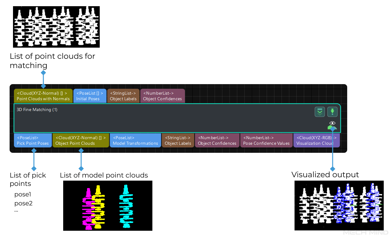
This Step can accurately match the point cloud model with the original point cloud and output more accurate poses of target objects. Please refer to Generate Point Cloud Model to create a point cloud template. )
Usage Scenario
This Step performs fine matching based on the matching results of 3D Coarse Matching and outputs more accurate object poses that can be used as pick points.
Parameters
Parameter Tuning Level
Default value: Basic
List of values: Basic, Advanced
Instruction: You can choose from the following two parameter tuning levels:
Basic Parameter Tuning Level
This section introduces the parameters in the Basic parameter tuning level, and these parameters are also available in the Advanced Parameter Tuning Level.
Model Settings
- Model Selection
-
Instructions: Click the drop-down button to select and apply a point cloud template and its corresponding geometric centers.
- Model File
-
Instructions: Click
 to select a point cloud template file in PLY format. You can use Matching Model and Pick Point Editor to easily generate, edit, and save point cloud templates and the corresponding geometric centers/pick points.
 - Geo Center Point File
-
Instructions: Click
 to select a geometric center file in JSON format. You can use Matching Model and Pick Point Editor to easily generate, edit and save point cloud templates and the corresponding geometric centers/pick points.
Cloud Orientation Calculation
- Point Orientation Calc Mode
-
Default value: Origin
Instruction: This parameter is used to specify the method to calculate the orientations of points in the point cloud. There are four methods as shown below. Please select one according to the actual situation of the project.
| Value list | Description |
|---|---|
Origin |
Directly obtain the normal from the point cloud model when the file contains the normal of the point cloud model directly. |
StandardMode |
Use the CPU to recalculate the normal direction of the input point cloud. It is recommended to use this mode when the model file doesn’t have normal direction: Search for the k points closest to the target, and use PCA (Principal Component Analysis) to obtain the minimum eigenvector as the point’s normal direction. |
EdgeTangent |
Calculate the tangent at the edge of the point cloud model and take the tangent as the normal. This method can distinguish different objects whose outer contours are mirror images of each other. This method is recommended when edge matching is performed on relatively flat objects. There are two example usage scenarios as follows: |
Scenario 1: The two sides of the object need to be distinguished. The 3D Fine Matching (Multiple Models) Step can be used, and there should be two model point cloud models corresponding to the two sides of the object respectively. |
|
Scenario 2: The two sides of the object need NOT to be distinguished. In this case, the 3D Fine Matching Step with one point cloud model is applicable. |
|
EdgeNormal |
Calculate the normal at the edge of the point cloud model. This method is recommended when edge matching is performed on relatively flat objects. |
|
When using the EdgeTangent or EdgeNormal methods, ensure that each edge point cloud does not contain multiple objects; in other words, each object point cloud is separated. |
- Number of Searching Points
-
Default value: 10
Instruction: This parameter is used to set the number of points in the vicinity of the target point to search for. The minimum value is 1.
Matching Method
Default value: GMM
Value list: GMM and nearest-neighbor.
Instruction: This parameter is used to select the local matching method to match the point cloud model with the scene point cloud. The point cloud model will move and rotate according to the set range to match the point cloud in the scene obtained in the previous step match.
Example: In most scenarios, GMM has better anti-interference ability and higher matching speed, so it is generally recommended; in rare cases when GMM cannot meet the demand, nearest-neighbor can be selected.
Settings under GMM
- Matching Mode
-
Default value: Standard
Value list: HighSpeed, Standard, and HighPrecision.
Instruction: There are three matching modes. Select the appropriate one according to the project requirements:
HighSpeed: the fastest but less accurate. Standard: relatively stable. HighPrecision: the most accurate but slower.
- Number of Iterations
-
Default value: 30
Instruction: Iteration refers to iteratively running a specific instruction until the conditions are met. The number of iterations refers to the number of repetitions of instruction running in this process. The parameter set here is the upper limit of the number of iterations. The larger the value is, the greater the number of times of matching calculations will be, which means a longer running time and higher accuracy.
- Standard Deviation
-
Default value: 3.000 mm
Instruction: The value here needs to match with the initial pose deviation. When the input initial pose deviation after the previous step (3D Coarse Matching) is greater, a larger Standard Deviation is required. In this case, the matching speed is faster.
Example: When the set value is larger than the initial pose deviation, there will be a great result deviation. As shown in the figure below, the Standard Deviation on the right is 40.000 mm, far greater than the initial pose deviation. You can see that the matching result on the right with an overly large standard deviation is less accurate. Normally, this value will be no greater than 10 mm.

For smaller workpieces, it is recommended to adjust the standard deviation to a smaller value for more accurate matching results.
- Standard Deviation Update Step Number
-
Default value: 3
Instruction: During the matching process, the Standard Deviation gradually decreases until it reaches the value of Minimum Standard Deviation. The number of times that the standard deviation decreases in this process is the value of this parameter. For some cases with large standard deviation, the more times of the decrease, the more stable the entire decrease process. Under normal circumstances, this parameter does not need to be adjusted.
- Speed Up on Large Object Quantities
-
Default value: Disabled.
Instruction: It is recommended to enable this option if there is a large number of objects in the scene. If this option is enabled, the Step will perform faster when there is a large number of objects. However, if the number of objects is small, the processing speed of the Step may be slowed down.
Settings under Nearest-Neighbor
Iteration Settings
- Nearest Point Search Radius
-
Default value: 10.000 mm
Value range: [1.000, +∞)
Instruction: This parameter is used to adjust the search radius of the nearest point (in mm), and the value setting should correspond to the input initial pose deviation. When the input initial pose deviation is large (the deviation between the scene point cloud and the point cloud model is large), this parameter needs to be increased; when the initial pose deviation is very small, this parameter can be adjusted to a small value. The minimum value that can be set for this parameter is 1.000 mm. If the radius is less than this lower limit, some sparsely distributed points may not find the closest point, which could affect the output result.
- MSE Threshold
-
Default value: 0.001
Instruction: This parameter (Mean Square Error Threshold) is used to adjust the upper limit of the mean square error. This value is recorded after each iteration and used for comparison in subsequent iteration steps. When the mean square error of an iteration is less than the set value, it is considered that the iteration effect has met the requirements and the iteration will be terminated.
- Window Size
-
Default value: 10
Value range: [3, +∞)
Instruction: This parameter refers to the number of consecutive iterations with small error fluctuations in the iterative optimization process. When this parameter is too small, a local optimal solution may appear, which affects the final matching accuracy. Example: If the window only contains the error of the results of three consecutive iterations, so the error trend can only be obtained by comparing the errors of the three iterations, which may lead to a local optimal solution (the error of the second iteration is less than the error of the first iteration and the first iteration) instead of a global optimal solution. According to the recommended value of the number of iterations which is 30, subsequent iterations with more significant error reduction may occur.
- Show Corresponse
-
Default value: Unselected.
Instruction: If it is selected, the corresponding points will be displayed in each iteration.
- Complex Object
-
Default value: Unselected.
Instruction: Selected if the target object is a complex-shaped object (not a simple geometric shape) or if the Automatic Weight function is required.
- Automatic Weight
-
Default value: Unselected.
Instruction: If it is selected, the weight of iteration points will be calculated automatically. It is recommended to use this function for objects with poor coarse matching results.
Point Pair Rejection
- Reject Pair
-
Default value: Unselected.
Instruction: This parameter decides whether to remove repeated point pairs. There are multiple point pairs in the process of searching for the nearest point, and sometimes the unwanted point pairs need to be filtered out. If this option is selected, this function will be used to remove them through configurating the following N Sigma Threshold and Point Pair Angle Diff Thre parameters; if not checked, these two parameters will not take effect during the matching process.
- N Sigma Threshold
-
Default value: 1.0000
Instruction: This parameter is the multiplier of the standard deviation threshold of the distance between each points. The point pair whose distance is outside N sigma will be eliminated.
- Point Pair Angle Diff Thre
-
Default value: 45°
Instruction: This parameter is the upper limit of the angle difference (in °) between the normals of two points in every matching point pair. If the angle difference is greater than this value, this point pair will be eliminated.
- Apply Weights on Pairs
-
Default value: Unselected.
Instruction: If it is selected, the weight of the model will be used in the iteration of the algorithm, so it is more likely to match better.
- Remove Repeat Correspond
-
Default value: Unselected.
Instruction: If it is selected, the function of removing repeating corresponding point pairs will be used, and the settings of Remove Repeat Correspond Type will take effect. It is recommended to use this function when the point cloud model has more points than that of a single object in the scene.
- Remove Repeat Correspond Type
-
Default value: MinDis
List of values: MinDis and GlobalMin
Instruction: This parameter is used to select the method of removing repeating corresponding point pairs. There are two methods in total:
MinDis: Calculate the distance between the repetitive point pairs. Then, keep the point pair with the smallest distance, and delete the remaining repetitive point pairs. More repeating corresponding point pairs will be eliminated in this method than the other. GlobalMin: Take the average value of the distance between the repetitive point pairs as a reference to find out the point pair whose distance is closest to the average value. Then, retain this point pair and eliminate others. Less repeating corresponding point pairs will be eliminated in this method than the other.
Sample Settings
- Sampling Interval
-
Default value: 5.000 mm
Instruction: This parameter is used for the downsampling of the model and scene point cloud. The bigger the interval, the less the point number of the sampled point cloud, and the lower the accuracy of model estimation.
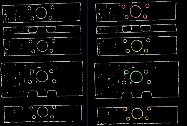
Example: The figure below shows the output results when Sampling Interval is set to 5.000 mm and 25.000 mm, respectively. The white parts are the input object point clouds, and the colored lines are the matching results. It can be seen from the comparison of the two pictures that the smaller the sampling interval is, the more accurate the output result will be.
Validation Settings
- Confidence Threshold
-
Default value: 0.500
Value range: [0, +∞)
Instruction: The confidence threshold is used to determine whether the matching result is valid. Matching results with confidences higher than the threshold are valid and those lower are not. A higher threshold leads to fewer valid matches, while the output results are more accurate. A lower threshold leads to more valid matches, while the output results are less accurate.
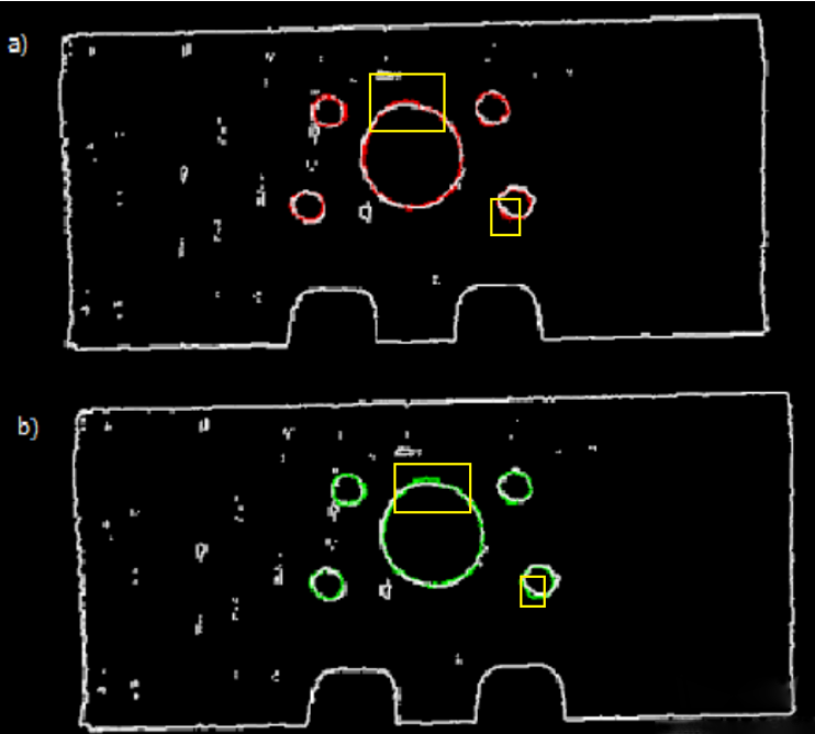
Example: In the figure below, the confidence threshold of (a) is 0.500, and that of (b) is 0.920. The match of (a) is more accurate than that of (b). It can be known that when the larger Confidence Threshold is, the more likely it is that results with higher matching accuracy are retained.
Even when a higher threshold is set, there may be no valid matching result to output. It may be because that different parts of the target object have the same shape.
- Search Radius
-
Default value: 10.000 mm
Value range: [0, +∞)
Instruction: The value of Search Radius affects the pose matching score. The higher the value of the Search Radius, the looser the criterion for evaluating the pose matching result will be, which means that even if the pose matching result is of poor quality, the pose matching score will be high; the lower the value of the Search Radius, the more strict the criterion for evaluating the pose matching result will be. Please set the value according to the actual situation of the point cloud. If the points in the point cloud are sparse, the Search Radius should be set slightly larger.
|
During parameter tuning, you can set an original Search Radius first and run the Step. Then you can check the matching result in the Debug Output window and compare the result with the pose matching score. If the matching result does not correspond with the matching score, please adjust the Search Radius according to the actual situation. |
Output Settings
- Maximum Number of Detected Poses in Each Point Cloud
-
Default value: 1
The larger the value, the more matches are generated.
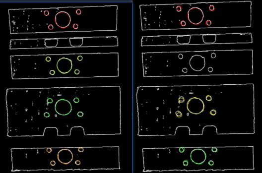
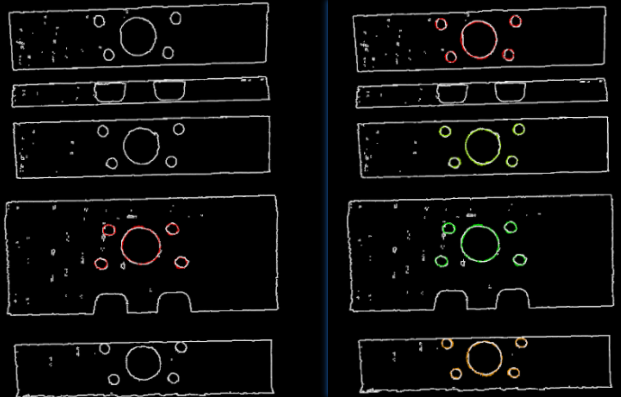
Instruction: The larger the value is, the more matching pairs will be output. The figure below shows the output results when this parameter is set to 1 (left) and 4 (right).
Results Visualization
- Show Matching Results
-
Default Value: Selected.
Instruction: If this option is selected, the output model and scene point cloud will be displayed.
Advanced Parameter Tuning Level
This chapter only introduces the parameters that Basic Mode does not contain. If there are some parameters that are the same as that in the Basic Mode, please refer to Basic.
Symmetry Settings
When a part of the workpiece to be recognized is symmetrical, you will need to adjust the symmetry settings to escape a local optimum of the matching result. An axis of the reference frame with the geometric center as its origin will be specified as the rotation axis, and the point cloud model will rotate around the specified axis according to the symmetry angle step and therefore the optimal matching result can be obtained.
- Symmetry Axis
-
Default value: ROTATE_BY_Z
List of values: ROTATE_BY_X, ROTATE_BY_Y, and ROTATE_BY_Z
Instruction: This parameter is used to select the symmetry rotation axis around which the initial pose is changed.
- Angle Step
-
Default value: 360°
Instruction: This parameter specifies the angle of rotational symmetry.
Example: If an object looks the same before and after rotating 60° around an axis, its angle of rotational symmetry is 60°.
- Min Rotation Angle
-
Default value: −180°
Instruction: This parameter is used to adjust the minimum rotation angle.
- Max Rotation Angle
-
Default value: 180°
Instruction: This parameter is used to adjust the maximum rotation angle.
- Example
-
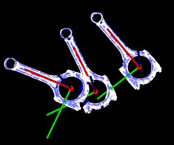
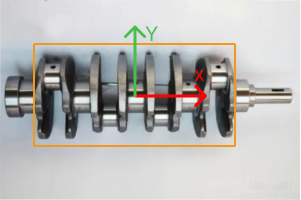
As shown in the figure below, the main part of the crankshaft, i.e., the part in the frame, has 180° rotational symmetry along the Y-axis.
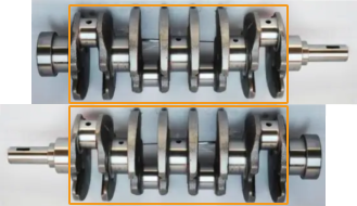
If you do not adjust the symmetry settings, there can be mismatches since the shapes of parts of the point cloud model and the crankshaft are similar, as shown below.
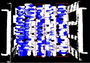
Only the middle part of the point cloud model and the crankshaft match with each other. However, if the point cloud model rotates 180°, it will match with the entire crankshaft, and the corresponding matching confidence will be higher.
After ROTATE_BY_Y (the Y-axis of the reference frame with the geometric center as its origin) is set as the Symmetry Axis, and the Angle Step is set to 180°, the point cloud model and the crankshaft match with each other correctly, as shown below.
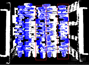
Pose Filtering Settings
- Filter Pose by Model Rotation Angle
-
Instruction: In the Edge Matching mode, the point cloud model may need to be rotated by a certain angle to match with the scene point cloud, and the posed will be filtered by the point cloud model’s rotation angle. When the model’s rotation angle exceeds the Angle Difference Upper Threshold, the pose will be filtered out.
Default value: Disabled.
- Angle Difference Upper Threshold
-
Instruction: See the tooltip of Filter Pose by Model Rotation Angle.
Default value: 135.000°
Model Weight in Validation
When the workpieces to be recognized have the similar main body, while their specific parts differ greatly, the weight of the “parts” should be higher to output a correctly matched result.
- File of Model Fragments with High Weight
-
Instruction: This file (PLY format) is a fragment of Model File. Based on the actual workpiece, determine which part is selected as the high weight file. The points in this file have a high weight set by the Weight of Each Point.
- Weight of Each Point
-
Default value: 2.0000
Instruction: This parameter is to set the weight value for the parts with salient features in the point cloud model. The initial weight of all points is 1. After setting this parameter for the target cloud, the weight coefficient of the target cloud will become 1Xthisparameter, so as to achieve the purpose of emphasis in the subsequent matching steps.
- Search Radius When Set Weight
-
Default value: 3.000 mm
Instruction: This parameter is used to set the radius for setting weights. The unit is millimeters. The weight setting is an operation performed on the original point cloud model. The point cloud model will be down-sampled before it is used in the matching process, which causes some points to be shifted or lost. In the process of setting the weight of the points near the missing point, the search radius needs to be set, and the search radius is set by this parameter.
Validation Settings
- Apply Angle Deviation in Validation
-
Default value: Unselected.
Instruction: If it is selected, the angle difference of the normal vector of the corresponding point pair will be considered in the pose validation process. In this case, although the output is often reduced, it could be more accurate.
- Multiply Corresponding Points Ratio in Scene
-
Default value: Unselected.
Instruction: If it is selected, the matching score will be multiplied by the proportional coefficient of the corresponding point to the scene point. It is not suitable for the case of estimating poses of multiple objects in one point cloud.
Results Visualization
- Show Sampled Model Cloud
-
Default value: Unselected.
Instruction: If it is selected, the sampled point cloud model will be visualized in the output.
- Show Sampled Scene Cloud
-
Default value: Unselected.
Instruction: If it is selected, the sampled scene point cloud will be visualized in the output.
- Show Validation Point Correspondences
-
Default value: Unselected.
Instruction: If it is selected, the corresponding relationship between the model and the scene point cloud will be visualized in the output.
